Supercharge Your Innovation With Domain-Expert AI Agents!

Cap feeding star wheel structure of cap screwing machine

A technology of capping machine and star wheel, which is applied in the direction of capping containers tightly with caps, threaded bottle caps, flanged bottle caps, etc. It can solve the problems of affecting work efficiency, time-consuming, inconvenient manual adjustment, etc., and achieves improvement. Work efficiency, easy to adjust the effect

Active Publication Date: 2022-05-13
GUANGZHOU PHARMA INTELLIGENT EQUIP CO LTD
View PDF10 Cites 0 Cited by
  • Summary
  • Abstract
  • Description
  • Claims
  • Application Information

AI Technical Summary

Benefits of technology

This patented technology allows for easier control over how much space inside an oven door lining needs to be kept clean during production. It uses a special device called a cup holder or bin hub mounted at one point along its length. A cylindrical part made from plastic fits around it's inner surface while another similar component holds other components like tubes. One side has holes where there connect to external pipings. Another side extends beyond this hole. When installing these parts together they form a sealed chamber within them. To install the cup holders, firstly position their bearings onto the stationery plate then insert bolts into bushings placed under the cups. Then, put the top rod on the standby machine back cover. By turning the motorized spool assembly, the thread goes round until all three wires have been twisted securely enough to transmit power signals. Afterwards, the rotation speed of the motors is controlled based upon the desired level of lift (the distance above). Finally, the elevator moves downward towards the baseplate, allowing the bowl seat to move closer to the main heater core. Once installed, the process starts again.

Problems solved by technology

This patented describes an apparatus called Capsule Machine (CAS) that can automatically separate different types of plastic containers from each other during manufacturing processes such as filling them with liquid medicine or closing it up properly after use. However, this process requires manual intervention when changing container sizes due to its fixed position on top of the conveyor belt.

Method used


Image

  • Cap feeding star wheel structure of cap screwing machine
  • Cap feeding star wheel structure of cap screwing machine
  • Cap feeding star wheel structure of cap screwing machine

Examples


Embodiment Construction

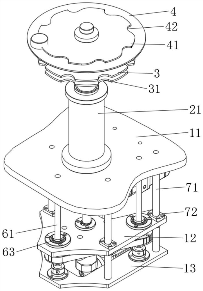
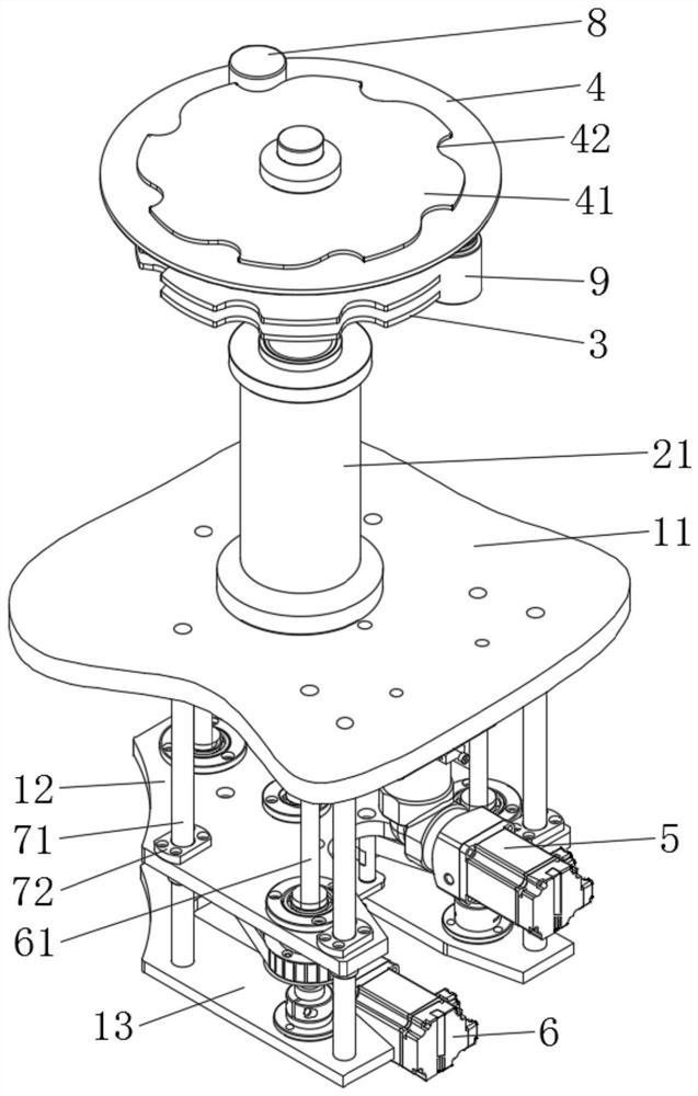
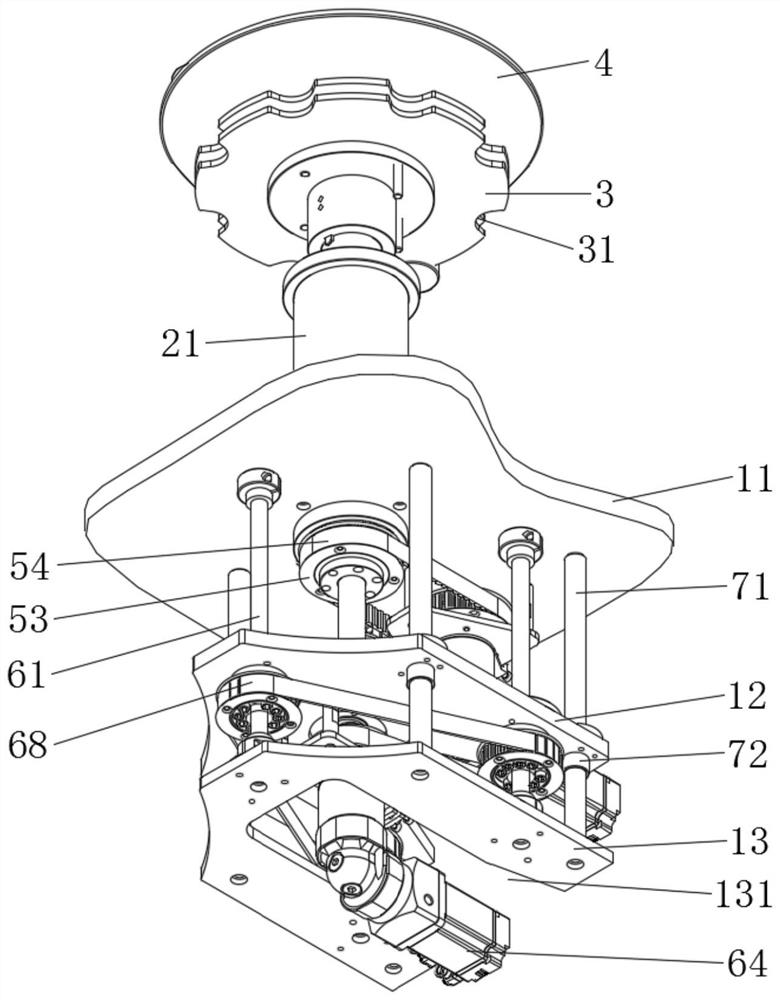
[0024] Figure 1 to Figure 7 A structural schematic diagram of a cap feeding star wheel structure embodiment of a capping machine provided by the present invention, including a fixed plate 11, a mounting plate 12, a bottom plate 13, a hollow fixed shaft 21, a shaft sleeve 22, a bottle output star wheel 3, a center Shaft 23, tray 4, sub-cover star wheel 41, rotary drive mechanism 5, lifting drive mechanism 6, mounting plate 12 is arranged between fixed plate 11 and base plate 13, fixed shaft 21 is arranged on fixed plate 11, inside fixed shaft 21 A shaft sleeve 22 is provided through the bearing, and the bottle-discharging star wheel 3 is sleeved on the shaft sleeve 22. The central shaft 23 is arranged in the shaft sleeve 22 through a key 24, and the two ends of the central shaft 23 extend out of the shaft sleeve 22 respectively. The upper end of 23 is provided with tray 4, and tray 4 is provided with sub-cover star wheel 41, and the lower end of central shaft 23 is rotatably a...


PUM


Abstract

The invention discloses a cap conveying star wheel structure of a cap screwing machine, which comprises a fixed plate, a mounting plate, a bottom plate, a hollow fixed shaft, a shaft sleeve, a bottle discharging star wheel, a central shaft, a tray, a cap separating star wheel, a rotary driving mechanism and a lifting driving mechanism, the mounting plate is arranged between the fixed plate and the bottom plate, and the fixed shaft is arranged on the fixed plate; a shaft sleeve is arranged in the fixed shaft through a bearing, the bottle outlet star wheel is sleeved on the shaft sleeve, the central shaft is arranged in the shaft sleeve through a key, two ends of the central shaft respectively extend out of the shaft sleeve, a tray is arranged at the upper end of the central shaft, a cap separating star wheel is arranged on the tray, and the lower end of the central shaft is rotatably arranged on a mounting plate. The rotation driving mechanism is arranged on the fixing plate and connected with the shaft sleeve to drive the shaft sleeve to rotate, and the lifting driving mechanism is arranged on the mounting plate and used for controlling the mounting plate to jack the center shaft. The height of the cover separating star wheel can be automatically adjusted, manual adjustment is not needed, adjustment is convenient, and the working efficiency is improved.

Description


Claims


Application Information

Patent Timeline
Owner GUANGZHOU PHARMA INTELLIGENT EQUIP CO LTD
Features
  • R&D
  • Intellectual Property
  • Life Sciences
  • Materials
  • Tech Scout
  • Unparalleled Data Quality
  • Higher Quality Content
  • 60% Fewer Hallucinations
Learn More