
Geotechnical grid laying operation device

A working device and geogrid technology, applied in soil protection, infrastructure engineering, construction, etc., can solve problems such as workers slipping

Active Publication Date: 2022-05-13
山东万泰新材料有限公司
View PDF10 Cites 0 Cited by
  • Summary
  • Abstract
  • Description
  • Claims
  • Application Information

AI Technical Summary

Problems solved by technology

[0004] In order to overcome the shortcomings that workers need to adjust the winding of the grid many times when laying the grid, and at the same time, it is easy for workers to slip when laying on a slippery slope, the invention provides a geogrid laying operation device

Method used


Image

  • Geotechnical grid laying operation device
  • Geotechnical grid laying operation device
  • Geotechnical grid laying operation device

Examples


Embodiment 1

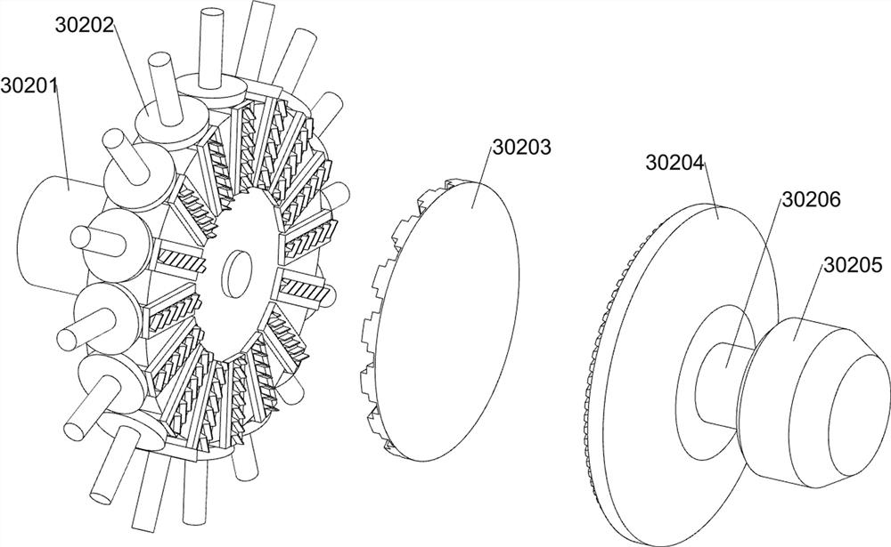
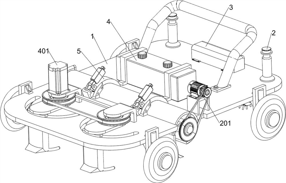
[0030] A geogrid laying operation device, according to Figure 1-13 As shown, it includes a car body 1, inserting nails 2, driving group 3, battery 4, connecting frame 5, collecting mechanism, laying mechanism and cleaning mechanism; the rear of the car body 1 is symmetrically detachably connected with two inserting nails 2 The rear part of the car body 1 is connected with a driving group 3, and the driving group 3 is located between two nails 2; the middle part of the car body 1 is connected with a battery 4; the front part of the car body 1 is symmetrically connected with two connecting frames 5 The car body 1 is connected with a collecting mechanism; the lower surface of the rear part of the car body 1 is connected with a laying mechanism; the front part of the car body 1 is connected with a cleaning mechanism.

[0031] Two motors are arranged symmetrically in the driving group 3 for driving the laying mechanism to run.

[0032] When working, the car body 1 is placed on th...

Embodiment 2

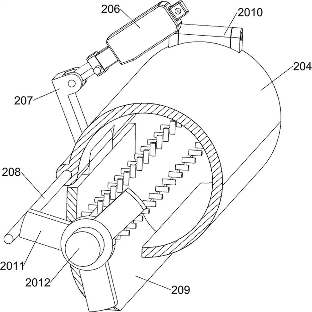
[0034] On the basis of Example 1, according to figure 1 with Figure 4-13 As shown, the collection mechanism includes a first motor 201, a first transmission wheel 202, a second transmission wheel 203, a collection cylinder 204, a first bracket 205, an electric push rod 206, a connecting shaft seat 207, a rotating rod 208, and a protective plate 209 , pinch plate 2010, second support 2011 and winding roller 2012; The middle part right side of car body 1 is welded with first support 205; The upper surface bolt of first support 205 is connected with first motor 201; The output of first motor 201 The shaft is fixedly connected with the first transmission wheel 202; the front part of the car body 1 is welded with a collection tube 204; the collection tube 204 is fixedly connected with the connecting frame 5; an electric push rod 206 is respectively installed on the two connecting frames 5; each Each telescoping part of the electric push rod 206 is connected with a connection shaft ...


PUM


Abstract

The invention relates to the field of geotechnical engineering, in particular to a geotechnical grid laying operation device. The technical problem is that a worker needs to adjust the rolling of the grid for multiple times when the grid is laid, and the worker is easy to slip when the grid is laid on a wet and slippery slope. According to the technical scheme, the geogrid laying operation device comprises a vehicle body, a laying mechanism and the like; a laying mechanism is connected to the rear lower surface of the vehicle body. According to the device, laying of the grating is achieved, soil blocks blocked in front of the device can be cleaned up during laying, fragments are prevented from entering the bottom of the device to affect laying, the road holding force can be adjusted according to the softness degree of the working ground, and the situation that the grating laying fails due to the fact that the device deviates in the direction when laying the grating is avoided.

Description

technical field [0001] The invention relates to the field of geotechnical engineering, in particular to a device for laying geotechnical grids. Background technique [0002] The existing geogrid laying requires two workers to release the rolled grid, and at the same time let a worker pull the grid to complete the laying. During the laying, the workers need to lift the rolled grid many times Move it so that another worker can pull the grid for laying, which is inefficient. At the same time, when encountering some slippery slopes, due to the limitation of the length of the grid, the grid cannot be directly rolled down from the top of the slope, so manual laying It is easy to slip and get injured when laying, and the laid grille is also easy to shift, the laying is not complete, and needs to be adjusted, which increases the difficulty of laying for workers and prolongs the construction period; [0003] To sum up, there is an urgent need for a geogrid laying operation device to...

Claims


Application Information

Patent Timeline
Patent Type & Authority Applications(China)
IPC IPC(8): E02D15/00E02D3/00
CPCE02D15/00E02D3/00Y02A40/22
Inventor 谭文乐
Owner 山东万泰新材料有限公司
Learn More