
Optical cable laying construction vehicle suitable for stony soil

A technology for laying optical cables and construction vehicles, applied in the field of telecommunication engineering, can solve the problems of poor flatness, difficult to obtain flexible application, etc.

Active Publication Date: 2020-04-10
QUZHOU UNIV
View PDF12 Cites 1 Cited by
  • Summary
  • Abstract
  • Description
  • Claims
  • Application Information

AI Technical Summary

Problems solved by technology

[0004] Since the direct underground laying of optical cables is often carried out in complex terrain areas, however, it is difficult for this kind of direct buried pipeline laying vehicle to be flexibly applied to complex construction sites, such as poor flatness and different widths. At the same time, for For rocky soil, it is necessary to add fine soil or sand to the bottom of the ditch to ensure the safety and reliability of optical cable laying

Method used


Image

  • Optical cable laying construction vehicle suitable for stony soil
  • Optical cable laying construction vehicle suitable for stony soil
  • Optical cable laying construction vehicle suitable for stony soil

Examples


Embodiment Construction

[0031] The following are specific embodiments of the present invention and in conjunction with the accompanying drawings, the technical solutions of the present invention are further described, but the present invention is not limited to these embodiments.

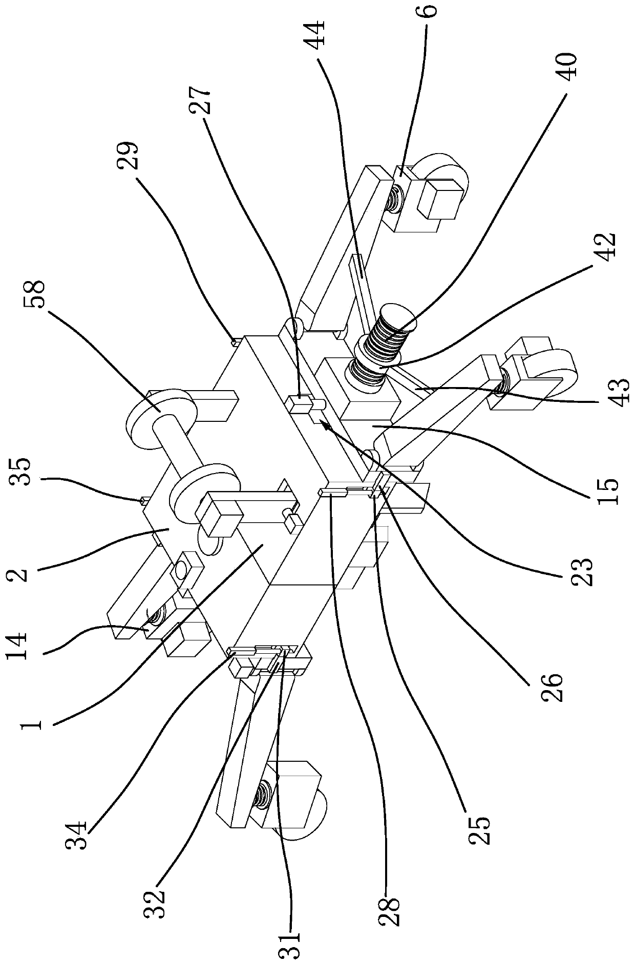
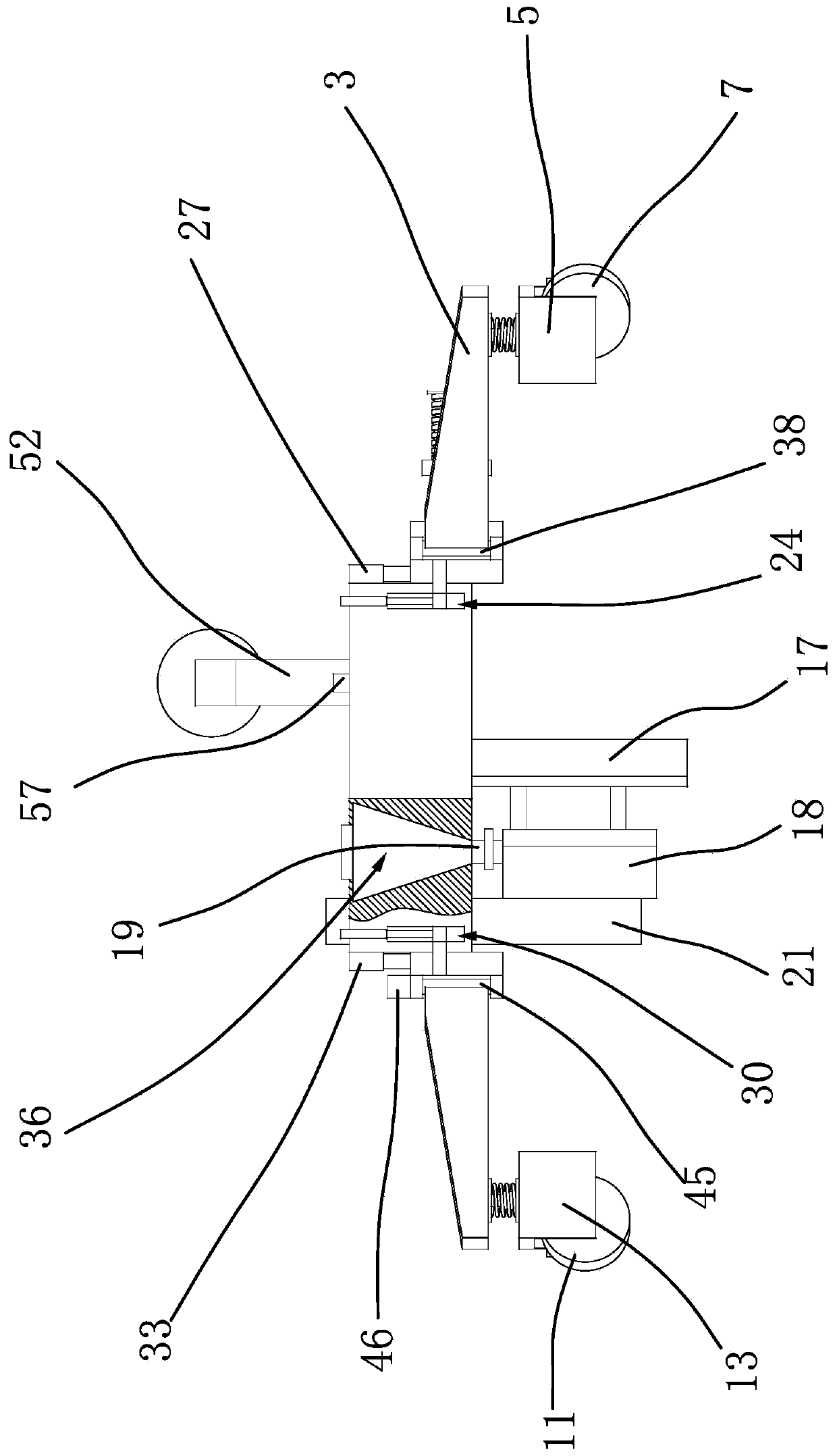
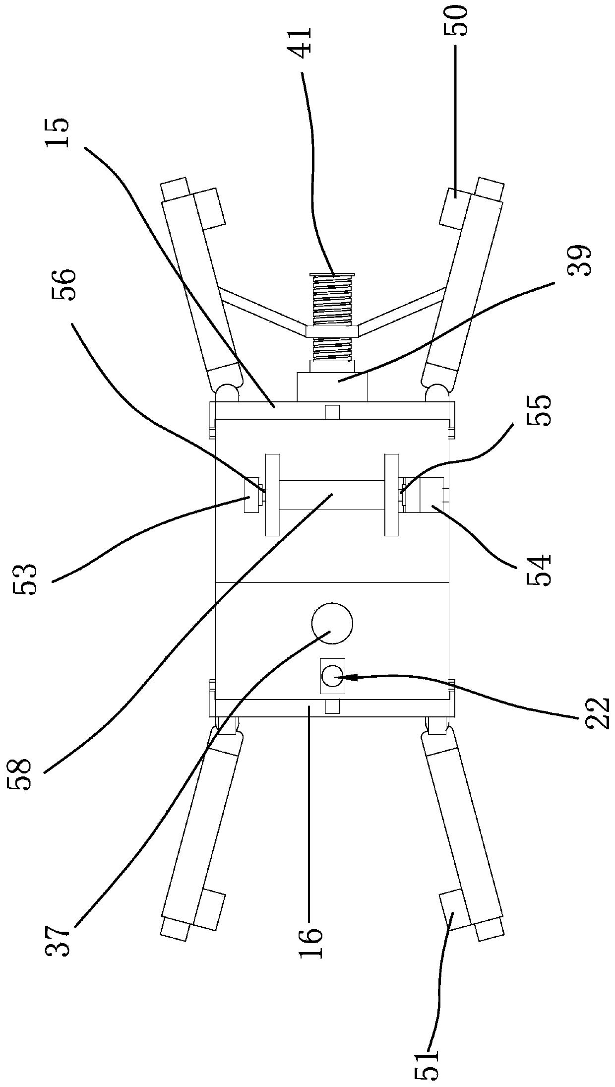
[0032] Such as figure 1 As shown, a construction vehicle for optical cable laying suitable for rocky soil comprises a car body, a wheel one 7, a wheel two 8, a wheel three 11 and a wheel four 12, the car body includes a front car body 1 and a rear car body 2, the front car body The car body 1 is provided with a power supply box and a controller. Front car body 1 and rear car body 2 are fixed, and front car body 1 is provided with mounting plate one 15 on the side of rear car body 2, and mounting plate one 15 is rotated and is provided with support one 3 and support two 4, and wheel One 7, wheel two 8 are respectively rotated and arranged on the support one 3, the support two 4, the rear body 2 is provided with the mountin...


PUM


Abstract

The invention provides an optical cable laying construction vehicle suitable for stony soil, and belongs to the field of telecommunication engineering. The optical cable laying construction vehicle suitable for stony soil comprises a vehicle body, a first wheel, a second wheel, a third wheel and a fourth wheel. The vehicle body comprises a front vehicle body and a rear vehicle body; a first mounting plate is arranged on the front vehicle body, a first support and a second support are rotationally arranged on the first mounting plate, the first wheel and the second wheel are rotationally arranged on the first support and the second support respectively, a second mounting plate is arranged on the rear vehicle body, a third support and a fourth support are rotationally arranged on the secondmounting plate, and the third wheel and the fourth wheel are rotationally arranged on the third support and the fourth support respectively; a primary furrowing coulter is fixed on the front vehicle body, a secondary furrowing coulter is arranged on the rear vehicle body, a wire guide plate is fixed on the secondary furrowing coulter, the upper end of the wire guide plate penetrates out of the upper surface of the rear vehicle body, and a wire guide through hole is vertically formed in the wire guide plate. The optical cable laying device has the advantage that optical cable laying at different depths can be achieved more flexibly according to complex terrains.

Description

technical field [0001] The invention belongs to the field of telecommunication engineering and relates to an optical cable laying construction vehicle, in particular to an optical cable laying construction vehicle suitable for rocky soil. Background technique [0002] There are many ways to lay outdoor optical cables, including underground pipeline laying, direct underground buried laying and overhead laying. Among them, direct underground laying is a method suitable for long-distance laying of optical cables outdoors. [0003] At present, manual construction is generally used for direct burial of optical cables, which is labor-intensive, labor-intensive, labor-intensive, low-efficiency, large damage area, and not conducive to environmental protection. Therefore, it is not suitable for the current rapid development of telecommunications engineering construction needs. Strength, improve work efficiency, after searching, for example, Chinese patent literature discloses a dire...

Claims


Application Information

Patent Timeline
Patent Type & Authority Applications(China)
IPC IPC(8): G02B6/50G02B6/54
CPCG02B6/50G02B6/504G02B6/54
Inventor 黄晓刚吕梅蕾
Owner QUZHOU UNIV
Learn More