Foundation pit support equipment for bridge foundation construction
A technology for foundation pit enclosure and bridge foundation, applied in infrastructure engineering, construction, excavation, etc., can solve problems such as short service life and slow construction speed, achieve good corrosion resistance, prolong service life, and increase construction speed Effect
- Summary
- Abstract
- Description
- Claims
- Application Information
AI Technical Summary
Problems solved by technology
Method used
Image

Examples
Embodiment 1
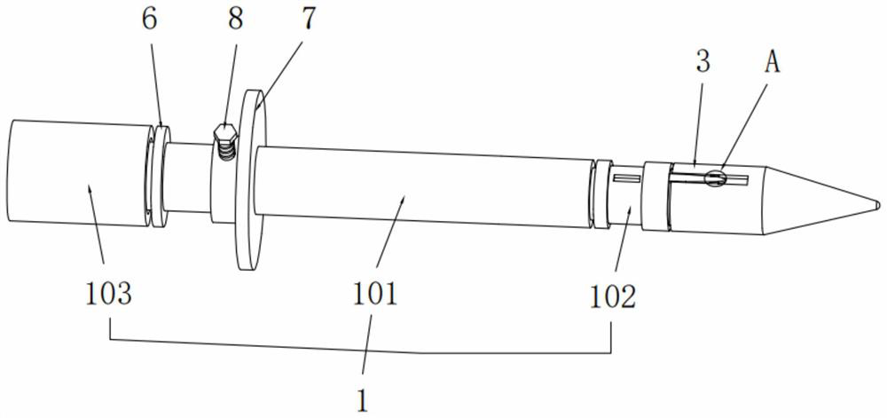
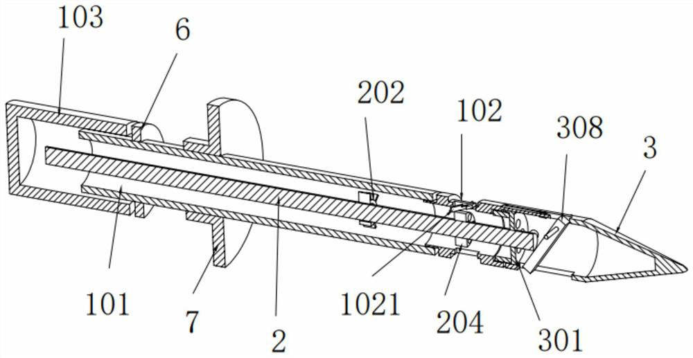
[0031] see Figure 1 to Figure 8 , the present invention provides a foundation pit protection equipment for bridge foundation construction, including soil nails 2 and a soil nail set 1 sleeved on the outside of the soil nails 2, the soil nail set 1 includes a main sleeve 101 and a positioning cylinder 102 , the positioning cylinder 102 is located at one end of the main sleeve 101, and the positioning cylinder 102 and the main sleeve 101 are connected by threads, the positioning cylinder 102 is provided with several movable baffles 1021, and the positioning cylinder 102 is provided with positions and The number of fixed slots 1022 corresponds to the number of movable stoppers 1021, and the end of the positioning cylinder 102 away from the main sleeve 101 is provided with a connecting rib 1023;
[0032]One end of the soil nail 2 is provided with a guide cap 3, and the end of the guide cap 3 near the soil nail 2 is provided with a baffle plate 301, and the baffle plate 301 is pro...
Embodiment 2
[0037] This embodiment is an explanation made on the basis of Embodiment 1. Specifically, please refer to figure 2 and Figure 8 , the guide cap 3 is a hollow structure, and the inner side of the guide cap 3 is provided with a limit block 308, and the limit block 308 is rotationally connected with the guide cap 3 through a pin shaft.
[0038] The guide cap 3 is a hollow structure, and a movable stop block 308 is provided in the guide cap 3. Under normal circumstances, the stop block 308 is arranged obliquely in the guide cap 3. When the soil nail 2 and the soil nail set 1 are driven After entering the soil body, continue to hammer the soil nail 2. At this time, the soil nail set 1 and the guide cap 3 do not move, while the soil nail 2 continues to move. When the soil nail 2 continues to move, the soil nail 2 will contact the limit block 308 conflict, and promote the movement of the limit block 308, the limit block 308 is eccentrically arranged, under the promotion of the soi...
Embodiment 3
[0041] This embodiment is an explanation made on the basis of Embodiment 1. Specifically, please refer to Figure 4 and Figure 5 The movable stopper 1021 is rotationally connected with the positioning cylinder 102 through a rotating shaft, and the end of the movable stopper 1021 close to the fixed groove 1022 is provided with a rubber gasket 1024, and the end of the movable stopper 1021 away from the rubber gasket 1024 is provided with a first stop protrusion From 1025. A fixing block 1026 is disposed in the fixing groove 1022 , and a plurality of protrusions 1027 are disposed at one end of the fixing block 1026 .
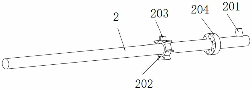
[0042] One end of the soil nail 2 close to the guide cap 3 is provided with a limit ring 202 , and the outer side of the limit ring 202 is provided with several limit stops 203 .
[0043] A movable stopper 1021 is provided in the positioning cylinder 102, and when the soil nailing set 1 is taken out, the movable stopper 1021 in the positioning cylinder 102 will ...
PUM
 Abstract
Description
Claims
Application Information
 - R&D
- Intellectual Property
- Life Sciences
- Materials
- Tech Scout
- Unparalleled Data Quality
- Higher Quality Content
- 60% Fewer Hallucinations
Browse by: Latest US Patents, China's latest patents, Technical Efficacy Thesaurus, Application Domain, Technology Topic, Popular Technical Reports.
© 2025 PatSnap. All rights reserved.Legal|Privacy policy|Modern Slavery Act Transparency Statement|Sitemap|About US| Contact US: help@patsnap.com