
Beam steel bar binding and mounting method

An installation method and beam reinforcement technology, which are applied in the processing of building materials, construction, building structure, etc., can solve problems such as major safety and quality hidden dangers, and achieve the goal of avoiding quality hidden dangers and installation hidden dangers, ensuring quality, and easy implementation. Effect

Pending Publication Date: 2022-05-13
CHINA CONSTR EIGHT ENG DIV CORP LTD
View PDF6 Cites 0 Cited by
  • Summary
  • Abstract
  • Description
  • Claims
  • Application Information

AI Technical Summary

Problems solved by technology

[0008] In order to overcome the defects existing in the prior art, a beam reinforcement binding and installation method is now provided to solve the problems of relatively large safety and quality hidden dangers in the existing beam binding installation construction method

Method used


Image

  • Beam steel bar binding and mounting method
  • Beam steel bar binding and mounting method
  • Beam steel bar binding and mounting method

Examples


Embodiment Construction

[0034] The application will be further described in detail below in conjunction with the accompanying drawings and embodiments. It should be understood that the specific embodiments described here are only used to explain related inventions, rather than to limit the invention. It should also be noted that, for ease of description, only parts related to the invention are shown in the drawings.

[0035] It should be noted that, in the case of no conflict, the embodiments in the present application and the features in the embodiments can be combined with each other. The present application will be described in detail below with reference to the accompanying drawings and embodiments.

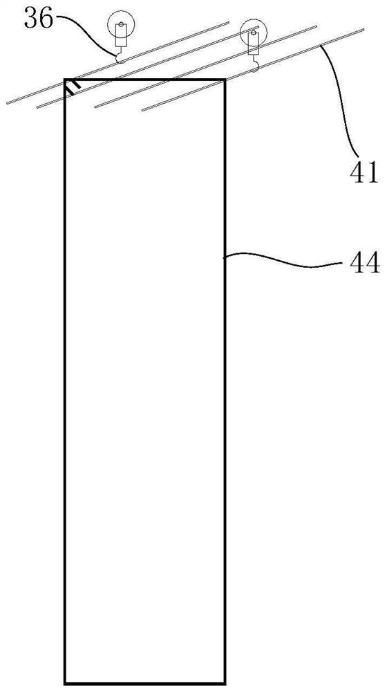
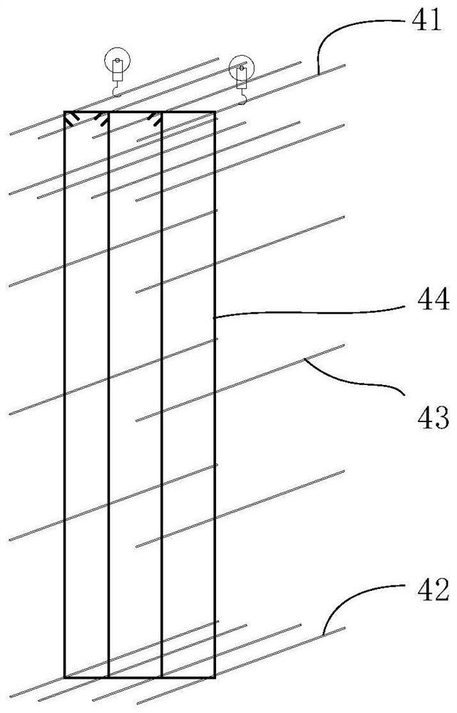
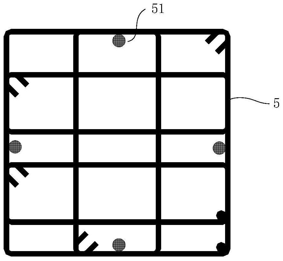
[0036] refer to Figure 1 to Figure 6 As shown, the present invention provides a beam reinforcement binding and installation method, comprising the following steps:

[0037] S1: erect multi-channel support frames 1 on the upper part of the beam bottom formwork (not shown in the drawings), the mul...


PUM


Abstract

The invention discloses a beam steel bar binding and mounting method which is simple and convenient to manufacture, assemble and implement, scientific and reasonable, capable of avoiding potential quality hazards and mounting hazards caused by a traditional beam steel bar binding and mounting method, capable of being popularized and applied to binding and mounting of beam steel bars on a large scale, good in use prospect and high in practicability. And the safety of the support frame body, the binding quality of beam bottom bars and the mounting quality of stirrups in a core area can be effectively ensured. The problem that an existing beam binding installation construction method has large safety and quality hidden dangers is solved.

Description

technical field [0001] The invention relates to the technical field of building construction, in particular to a beam reinforcement binding and installation method. Background technique [0002] The traditional beam reinforcement binding and installation method is to set up a frame support or set a square bar support on the beam bottom formwork surface, and bind the beam reinforcement on the frame body or square bar. After the binding is completed, remove the frame body or support square. bars, the beam automatically sinks, and the installation of the beam reinforcement is completed. [0003] There are certain defects in the binding and installation method of this beam reinforcement: [0004] After removing the frame body or supporting square bars, the beam steel bar falls freely, which will cause a huge impact on the bottom formwork of the beam and the supporting frame body, and there are certain potential safety hazards. [0005] After the beam steel bar falls freely, it...

Claims


Application Information

Patent Timeline
IPC IPC(8): E04G21/12E04G21/16E04G21/18
CPCE04G21/12E04G21/123E04G21/162E04G21/185Y02E10/20
Inventor 王亮代虎聂向东付恒得秦兴宽陈庆立陈自念
Owner CHINA CONSTR EIGHT ENG DIV CORP LTD
Learn More