Equipment and method for measuring iron loss of high-speed permanent magnet motor

A technology of permanent magnet motor and iron loss, which is applied in the direction of measuring electricity, devices using electric/magnetic methods, and measuring electric variables, etc. It can solve problems such as motor crashes, system crashes, and changes in the resistance value of motor windings, etc., to achieve Effects of reduced influence, reduced deviation, and easy maintenance of constant speed

Pending Publication Date: 2022-05-13
ZHEJIANG UNIV
View PDF0 Cites 0 Cited by
  • Summary
  • Abstract
  • Description
  • Claims
  • Application Information

AI Technical Summary

Problems solved by technology

However, high-speed motors also have some outstanding problems. High power density also leads to high power loss density. At the same time, because high-speed motors work under high-frequency alternating magnetic fields, the temperature rise of the motor is greatly increased compared with ordinary motors. In severe cases, it may The demagnetization of the permanent magnet will cause the motor to collapse, and the main cause of the temperature rise is the loss of the motor. The measurement method of the mechanical loss is relatively mature, and the method of measuring the high-speed iron loss by the experiment method needs to be improved. The high-speed motor iron loss can be accurately measured through the experiment. There are still big challenges
[0003] The existing equipment and methods for measuring the iron loss of high-speed motors through experiments do not consider the change of the resistance value of the motor windings of high-speed motors at high frequencies. There are research methods. When setting up the control group experiment, the control variables required in the experiment cannot be guaranteed, such as through the locked rotor method. When the motor equivalent circuit is inconsistent with the rated working condition after the rotor is locked, it is equivalent to studying two motors. Simultaneously The rotor of the motor is fragile and subject to external disturbances, it is easy to cause the system to crash

Method used


Image

  • Equipment and method for measuring iron loss of high-speed permanent magnet motor
  • Equipment and method for measuring iron loss of high-speed permanent magnet motor
  • Equipment and method for measuring iron loss of high-speed permanent magnet motor

Examples


Embodiment Construction

[0037] The following will clearly and completely describe the technical solutions in the embodiments of the present invention with reference to the accompanying drawings in the embodiments of the present invention. Obviously, the described embodiments are only some, not all, embodiments of the present invention. Based on the embodiments of the present invention, all other embodiments obtained by persons of ordinary skill in the art without making creative efforts belong to the protection scope of the present invention.

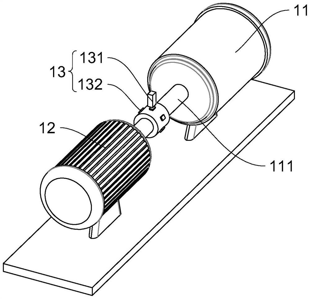
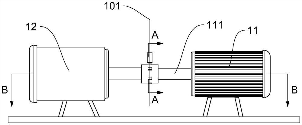
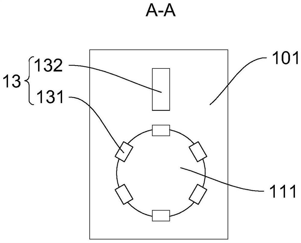
[0038] refer to Figure 1 to Figure 4 , a device for measuring the iron loss of a high-speed permanent magnet motor, comprising: a driving motor 11 , a motor to be tested 12 , a non-contact sensor 13 and a temperature sensor 14 . Wherein, the driving motor 11 includes a shaft 111 and a stator 112 , the shaft 111 rotates around the axis, and the stator 112 is provided with a winding 113 . The motor 12 to be tested includes a first unmagnetized permanent magnet...


PUM


Abstract

The invention discloses equipment for measuring iron loss of a high-speed permanent magnet motor. The equipment comprises a driving motor, a motor to be measured, a non-contact sensor and a temperature sensor. Wherein the driving motor comprises a shaft and a stator, the shaft rotates around the axis, and a winding is arranged on the stator. The to-be-tested motor comprises an unmagnetized first permanent magnet, and the to-be-tested motor and the driving motor are coaxially arranged. The non-contact sensor can measure the rotating speed of the shaft without contacting the shaft. The temperature sensor is arranged on the stator and used for measuring the temperature of the winding. The iron loss of the to-be-tested motor is calculated by controlling whether the first permanent magnet is magnetized or not, controlling the rotating speed of the shaft to be constant, recording the input power difference value of the driving motor before and after the first permanent magnet is magnetized, and recording the temperature difference value of the winding. The method mainly solves the problem that a traditional method for measuring the iron loss of the high-speed permanent magnet motor lacks consideration of copper loss and lacks control variables.

Description

technical field [0001] The invention relates to the technical field of electric power transmission, and more specifically, relates to a method for measuring the iron loss of a high-speed permanent magnet motor. Background technique [0002] High-speed permanent magnet synchronous motors are widely used in industries such as gas compressors, distributed power generation, electrical turbocharging, turbines, and flywheel energy storage systems due to their high power density, compact size, high efficiency, and suitability for high-speed direct drive applications without gearboxes field. However, high-speed motors also have some outstanding problems. High power density also leads to high power loss density. At the same time, because high-speed motors work under high-frequency alternating magnetic fields, the temperature rise of the motor is greatly increased compared with ordinary motors. In severe cases, it may The demagnetization of the permanent magnet will cause the motor t...

Claims


Application Information

Patent Timeline
Patent Type & Authority Applications(China)
IPC IPC(8): G01R31/34G01K13/00G01P3/44
CPCG01R31/343G01K13/00G01P3/44
Inventor 方攸同罗超马吉恩邱麟许博文陈建尹寿佳波
Owner ZHEJIANG UNIV
Why Eureka
Try Eureka