Optical image capturing system

An optical imaging system, the technology of the side of the image, applied in the fields of optics, optical components, instruments, etc., can solve the problems of the miniaturization of the telephoto lens and the inability to take into account the high pixels

Pending Publication Date: 2022-05-13
ZHEJIANG SUNNY OPTICAL CO LTD
View PDF0 Cites 0 Cited by
  • Summary
  • Abstract
  • Description
  • Claims
  • Application Information

AI Technical Summary

Problems solved by technology

[0004] The main purpose of the present invention is to provide an optical imaging system to solve the problem that the miniaturization and high pixel of the telephoto lens in the prior art cannot be balanced

Method used


Image

  • Optical image capturing system
  • Optical image capturing system
  • Optical image capturing system

Examples


Embodiment 1

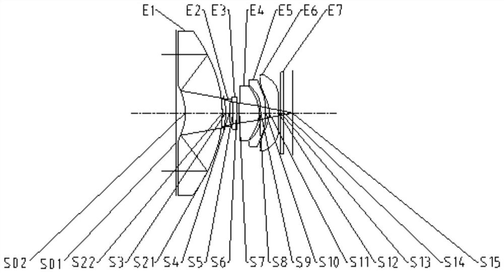
[0054] Such as Figure 1 to Figure 16 As shown, from the object side of the optical imaging system to the image side of the optical imaging system, it includes a first lens, a second lens, a third lens, a fourth lens, a fifth lens and a sixth lens, and the first lens includes a first transmission surface , a first reflective surface, a second reflective surface, and a second transmissive surface, the first transmissive surface is arranged on the outer peripheral region of the object side of the first lens, and the first reflective surface is arranged on the outer peripheral region of the image side of the first lens, The second reflective surface is arranged in the paraxial region of the object side of the first lens, and the second transmissive surface is arranged in the paraxial region of the image side of the first lens; the second lens has a negative power; the third lens has a negative power degree; the fourth lens has a positive power; the fifth lens has a power; the six...

Embodiment 2

[0072] Such as Figure 1 to Figure 16 As shown, from the object side of the optical imaging system to the image side of the optical imaging system, it includes: a first lens, a second lens, a third lens, a fourth lens, a fifth lens, and a sixth lens, and the first lens includes a first transmission surface, a first reflective surface, a second reflective surface, and a second transmissive surface, the first transmissive surface is arranged on the outer peripheral region of the object side of the first lens, and the first reflective surface is arranged on the outer peripheral region of the image side of the first lens , the second reflective surface is arranged in the paraxial region of the object side of the first lens, and the second transmissive surface is arranged in the paraxial region of the image side of the first lens; the second lens has a negative power; the third lens has a negative light Power; the fourth lens has a positive power; the fifth lens has a power; the si...


PUM


Abstract

The invention provides an optical imaging system, from an object side of the optical imaging system to an image side of the optical imaging system, a first transmission surface is arranged in an outer circumferential area of an object side surface of a first lens, and a first reflection surface is arranged in an outer circumferential area of an image side surface of the first lens. The second reflecting surface is arranged in a paraxial region of the object side surface of the first lens, and the second transmitting surface is arranged in a paraxial region of the image side surface of the first lens; the second lens has negative focal power; the third lens has negative focal power; the fourth lens has positive focal power; the fifth lens has focal power; the sixth lens has negative focal power; light is incident through the first transmission surface in sequence, is reflected to the second reflection surface through the first reflection surface, is reflected to the second transmission surface through the second reflection surface and then enters the second lens; the total length TTL of the optical imaging system and the effective focal length f of the optical imaging system meet the following conditions: 37.5 mmlt; f * f / TTLlt; and the thickness is 46.5 mm. According to the invention, the problem that miniaturization and high pixel of a telephoto lens in the prior art cannot be considered at the same time is solved.

Description

technical field [0001] The present invention relates to the technical field of optical imaging equipment, in particular to an optical imaging system. Background technique [0002] With the continuous iteration of mobile phone lenses, some people's demand for telephoto lenses is becoming more and more urgent. The greater the magnification of the telephoto lens, the larger the modules required in the mobile phone, which limits the development of mobile terminals in the direction of thinner and lighter. In order to reduce the size of the module, the size of the chip can be reduced, but reducing the chip means sacrificing pixels. [0003] That is to say, the telephoto lens in the prior art has the problem that miniaturization and high pixel cannot be balanced. Contents of the invention [0004] The main purpose of the present invention is to provide an optical imaging system to solve the problem that miniaturization and high pixels of the telephoto lens cannot be balanced in...

Claims


Application Information

Patent Timeline
IPC IPC(8): G02B13/00G02B13/18G02B17/08
CPCG02B13/0045G02B13/0055G02B17/086G03B30/00
Inventor 张晓彬闻人建科戴付建赵烈烽
Owner ZHEJIANG SUNNY OPTICAL CO LTD
Why Eureka
Try Eureka