
Voltage transformer expander with top wiring

A technology of voltage transformer and expander, which is applied in the direction of inductor, transformer/inductor cooling, transformer/inductor shell, etc., can solve the problems such as inability to adjust flexibly, inconvenient wiring, and inability to realize arbitrary direction rotation of primary terminals, etc. Achieve the effect of meeting the requirements of one-time terminal adjustment

Pending Publication Date: 2022-05-13
DALIAN NORTH INSTR TRANSFORMER GROUP
View PDF0 Cites 0 Cited by
  • Summary
  • Abstract
  • Description
  • Claims
  • Application Information

AI Technical Summary

Problems solved by technology

[0002] The primary terminal of the conventional structure of some potential transformers is welded on the bottom plate of the expander (such as Image 6 As shown), it is a horizontal wiring method, but in actual production, some users pointed out that this wiring method is inconvenient to connect, and it is impossible to realize the arbitrary rotation direction of the primary terminal, and it cannot be adjusted flexibly during on-site installation. It is hoped for further improvement

Method used


Image

  • Voltage transformer expander with top wiring
  • Voltage transformer expander with top wiring
  • Voltage transformer expander with top wiring

Examples


Embodiment 1

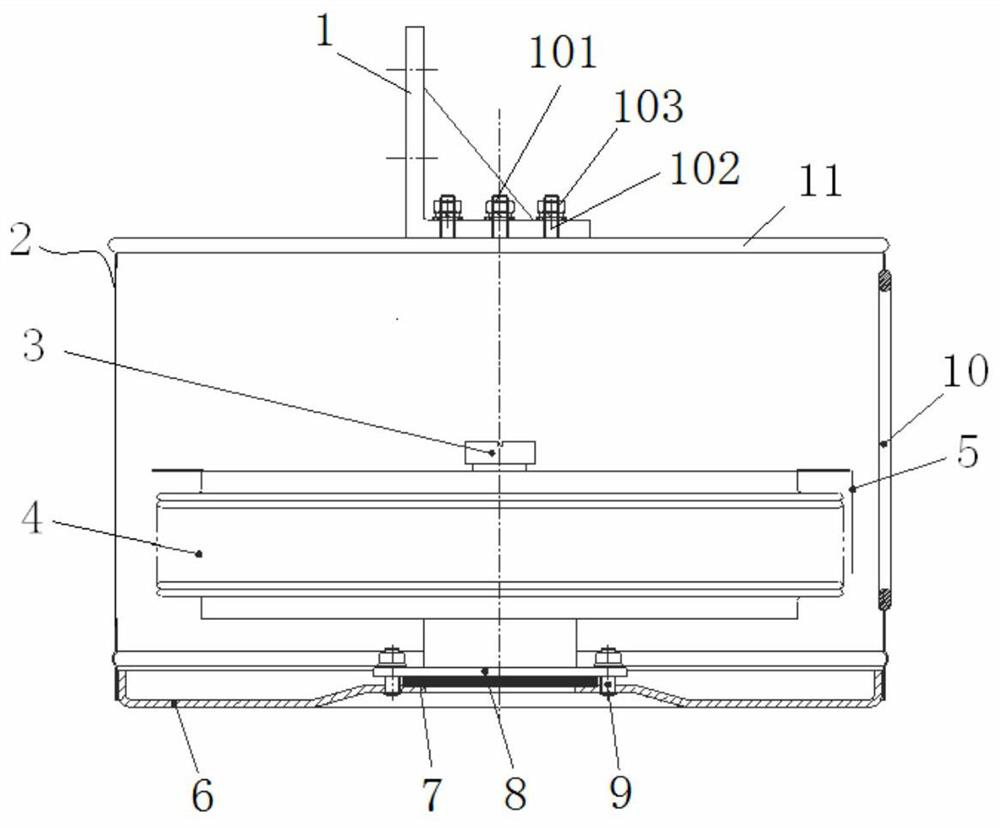
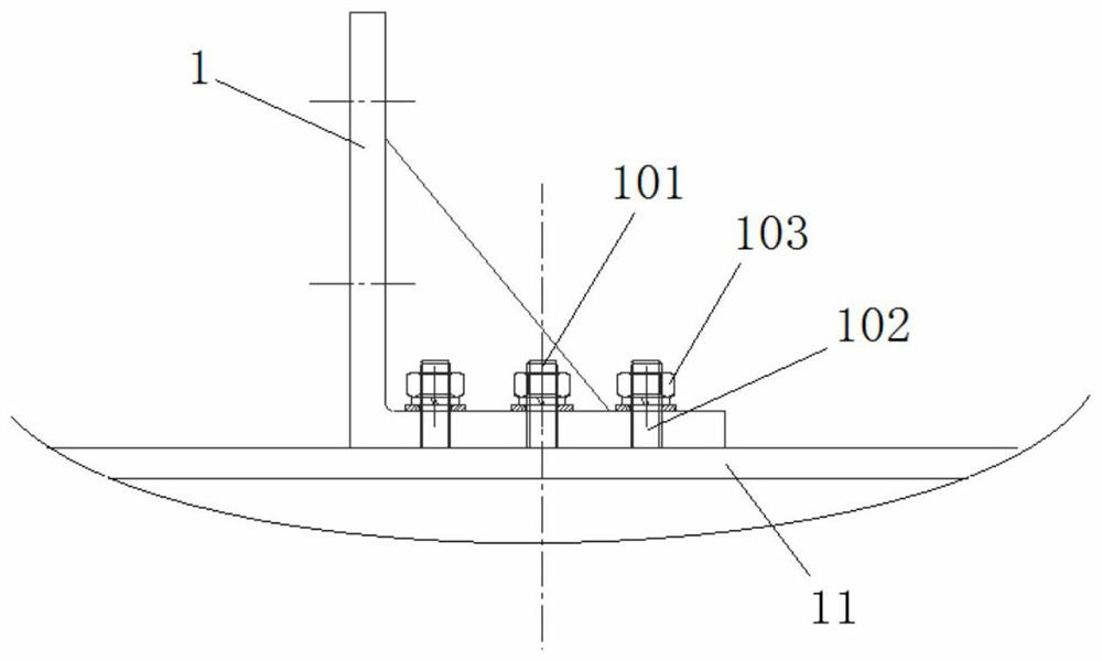
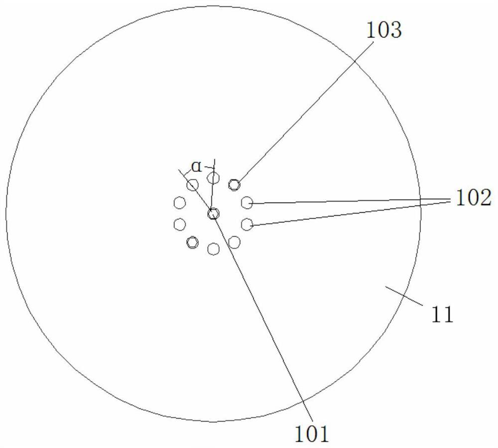
[0025] like Figure 1~3 As shown, in this embodiment, each screw 102 is arranged in the middle of the top plate 11 of the housing 2 in an annular shape, and a central rotating shaft 101 is provided at the annular center of the screw 102, and the horizontal side of the upper terminal board 1 except In addition to the annular through holes corresponding to each screw rod 102, a central hole corresponding to the central rotating shaft 101 is also provided at the circular center of the through hole, and the central rotating shaft 101 and each screw rod 102 pass through. On the horizontal side of the upper terminal board 1 , the compression nut 103 is set on the central rotating shaft 101 and the corresponding screw rod 102 to compress and fix the horizontal side of the upper terminal board 1 .

[0026] The working principle of this embodiment is:

[0027] like Figure 2~3 As shown, the angle between the adjacent through holes of the upper terminal board 1 is α, compared to Imag...

Embodiment 2

[0029] like Figure 4~5 As shown, the difference between this embodiment and Embodiment 1 is that in this embodiment, four screw rods 102 arranged in a square shape are arranged in the middle of the top plate 11 of the housing 2, and the central rotating shaft 101 is not provided. The horizontal side is provided with four square through holes corresponding to the screw rod 102. During installation, the upper terminal board 1 can be adjusted along four horizontal directions at an integer multiple of 90 degrees to meet customer requirements. After the position of the upper terminal board 1 is determined, the four screw rods 102 are fitted with compression nuts 103 to compress and fix the horizontal side of the upper terminal board 1 .


PUM

PropertyMeasurementUnit
thicknessaaaaaaaaaa

Abstract

The invention relates to the field of voltage transformers, in particular to a top wiring type voltage transformer expander which comprises a shell and an expander corrugated pipe, the expander corrugated pipe is arranged in the shell, an oil injection valve is arranged at the upper end of the expander corrugated pipe, an oil level indication mark is arranged on one side of the expander corrugated pipe, and an oil level indicator is arranged on the other side of the expander corrugated pipe. An inspection window corresponding to the oil level indication mark is arranged on one side of the shell, a plurality of screw rods are fixedly arranged in the middle of a top plate of the shell, the upper terminal plate is L-shaped, a plurality of through holes are formed in the horizontal side of the upper terminal plate, each screw rod penetrates through the corresponding through hole in the horizontal side of the upper terminal plate, and the upper terminal plate is fixedly connected with the upper terminal plate. The horizontal side of the upper terminal plate is sleeved on the corresponding screw rod through a compression nut to be compressed and fixed, and the primary wiring is fixedly connected with the vertical side of the upper terminal plate. The upper terminal plate capable of being rotationally adjusted is arranged in the middle of the top plate of the shell, so that the purpose of wiring at the top end of the expander is achieved, and the requirement for primary terminal turning is met.

Description

technical field [0001] The invention relates to the field of voltage transformers, in particular to a top-connected voltage transformer expander. Background technique [0002] The primary terminal of the conventional structure of some potential transformers is welded on the bottom plate of the expander (such as Image 6 As shown), it is a horizontal wiring method, but in actual production, some users pointed out that this wiring method is inconvenient to connect, and it is impossible to realize the arbitrary rotation direction of the primary terminal, and it cannot be adjusted flexibly during on-site installation. It is hoped for further improvement . Contents of the invention [0003] The purpose of the present invention is to provide a top-connected voltage transformer expander. By providing a rotatable and adjustable upper terminal plate in the middle of the top plate of the housing, the purpose of the top connection of the expander is realized, and the requirement for ...

Claims


Application Information

Patent Timeline
Patent Type & Authority Applications(China)
IPC IPC(8): H01F27/29H01F27/02H01F27/14H01F38/26
CPCH01F27/29H01F27/02H01F27/14H01F38/26
Inventor 李涛昌牟庆飞赵国庆张长江张俊伟李冰孙玉龙于治平哈元亮夏君宇张志庚
Owner DALIAN NORTH INSTR TRANSFORMER GROUP
Learn More