
A toroidal inductor automatic winding device

A ring-shaped inductor and automatic winding technology, which is applied in the manufacture of inductors, fixed inductors, inductors/transformers/magnets, etc., can solve the problems of long pause time, reduced winding efficiency, and low winding efficiency, and achieve action The effect of simplicity, quality improvement, and winding efficiency improvement

Active Publication Date: 2022-07-15
SHENZHEN GUDIAN ELECTRONICS
View PDF4 Cites 0 Cited by
  • Summary
  • Abstract
  • Description
  • Claims
  • Application Information

AI Technical Summary

Problems solved by technology

[0003] There is a pause between the actions of the two clamping arms, and the number of winding coils of the inductor is large. Accumulated, the pause time is long, resulting in low winding efficiency.
[0004] During the winding process, whether it is clamp arm a or clamp arm b, when pulling the enameled wire to move, it is necessary to pull all the parts of the enameled wire that are not wound on the skeleton to move, which further reduces the winding efficiency
[0005] In addition, the enameled wire keeps passing through the hook of clamp arm a and the clamp of clamp arm b, resulting in unnecessary bending loss and affecting the quality of the inductor

Method used


Image

  • A toroidal inductor automatic winding device
  • A toroidal inductor automatic winding device
  • A toroidal inductor automatic winding device

Examples


Embodiment Construction

[0055] In order to further illustrate the technical means and effects adopted by the present invention to achieve the predetermined purpose of the invention, the specific embodiments, structures, features and effects of the present invention are described in detail below in conjunction with the accompanying drawings and preferred embodiments.

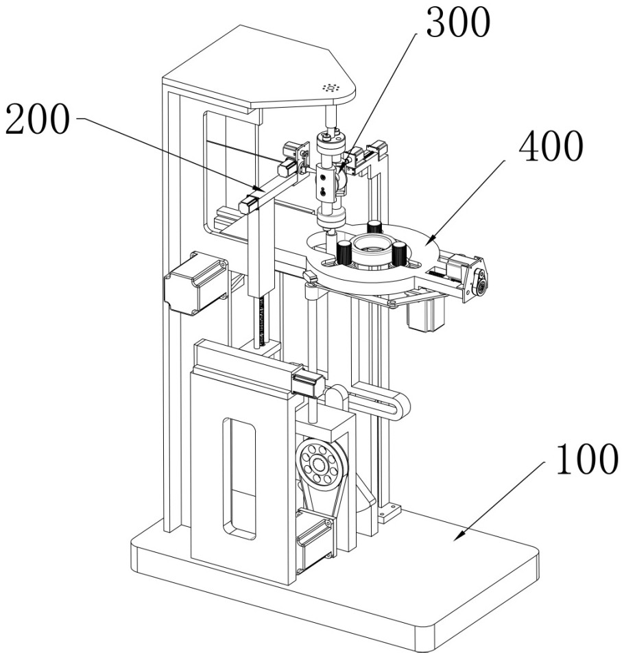
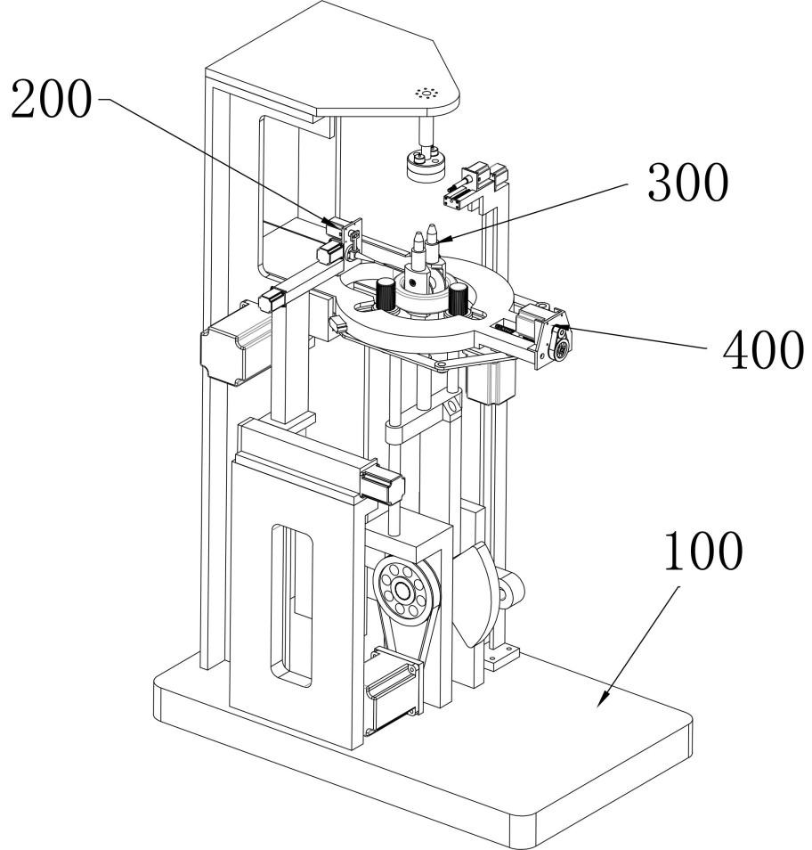
[0056] Inductors, including skeleton and winding (enameled wire), etc., the skeleton is generally in the shape of a ring, and the enameled wire is wrapped around the skeleton.

[0057] like Figure 1-7 As shown, an automatic winding device for a toroidal inductor includes a rack 100, and a wire feeding device 200, a wire winding device 300 and a clamping device 400 are installed on the frame 100, wherein the wire feeding device 200 is used for winding The device 300 conveys the enameled wire, the winding device 300 is used for orderly winding and storing the enameled wire and pulling the wound enameled wire to reciprocate up and down in...


PUM


Abstract

The invention relates to an automatic winding device for annular inductors, which belongs to the technical field of automatic winding of inductors. The enameled wire is conveyed to the winding device. The winding device is used for orderly winding and storing the enameled wire and pulling the wound enameled wire to reciprocate up and down in the vertical direction. The clamping device is used to clamp the frame and pull the frame to reciprocate in the horizontal direction. The traction skeleton rotates around its own axis; compared with the prior art, in this solution, the winding action consists of the up and down reciprocating movement of the enameled wire and the horizontal reciprocating movement and rotation of the skeleton. The action is simple and the winding efficiency is significantly improved. Outside the surrounding skeleton, there is no other bending loss, and the quality of the inductor is significantly improved.

Description

technical field [0001] The invention relates to the field of manufacture of inductors, in particular to the field of automatic winding of inductors, and in particular to an automatic winding device of annular inductors. Background technique [0002] In the existing automatic winding technology of inductors, it is generally realized by the cooperation of two sets of clamping arms. Figure 23 As shown, clamp arm a moves from bottom to top and hooks the enameled wire, pulls the enameled wire to move down through the skeleton in the direction of a, then, clamp arm b clamps the enameled wire and pulls the enameled wire to move to the top of the skeleton along the b direction, and so on and so forth, With the rotation of the skeleton, the automatic winding of the inductor is realized. [0003] There is a pause between the actions of the two clamping arms, and the number of windings of the inductor is large, which accumulates and the pause time is long, resulting in low winding eff...

Claims


Application Information

Patent Timeline
Patent Type & Authority Patents(China)
IPC IPC(8): H01F41/098H01F41/082H01F41/096H01F37/00
CPCH01F41/098H01F41/096H01F41/082H01F37/00
Inventor 徐麟刘世盛陈海斌曹长根王强
Owner SHENZHEN GUDIAN ELECTRONICS
Learn More