Locking mechanism

A locking mechanism and locking position technology, applied to structural parts, electrical components, battery pack parts, etc., can solve the problems of manual maintenance, short life, high unit cost, etc.

Pending Publication Date: 2022-05-13
北京胜能能源科技有限公司
View PDF0 Cites 2 Cited by
  • Summary
  • Abstract
  • Description
  • Claims
  • Application Information

AI Technical Summary

Problems solved by technology

[0002] With the development of my country's new energy electric vehicle technology, users have higher requirements for the cruising range and charging time of electric vehicles, but due to the battery system and battery characteristics, it is currently impossible to charge in a short period of time to reach Larger cruising range, when the battery fast charging technology cannot be further improved, it becomes particularly important for electric vehicles to quickly replace the battery pack
[0003] At present, several locking mechanisms commonly used in battery pack replacement solutions mainly include snap-on, tension-on, and screw-on, but the above-mentioned locking mechanisms still have the following defects during use, for example, the snap-on locking mechanism wears out during use Larger, easy to get stuck, and requires frequent manual maintenance; due to the large number of parts and complex structure, the tension-type locking mechanism has high requirements for battery pack matching, poor compatibility, and high unit cost; while the screw-type lock The compatibility of the stop mechanism is poor, there is no tolerance capability, and the parts are easily damaged and the service life is short

Method used


Image

  • Locking mechanism
  • Locking mechanism
  • Locking mechanism

Examples


Embodiment Construction

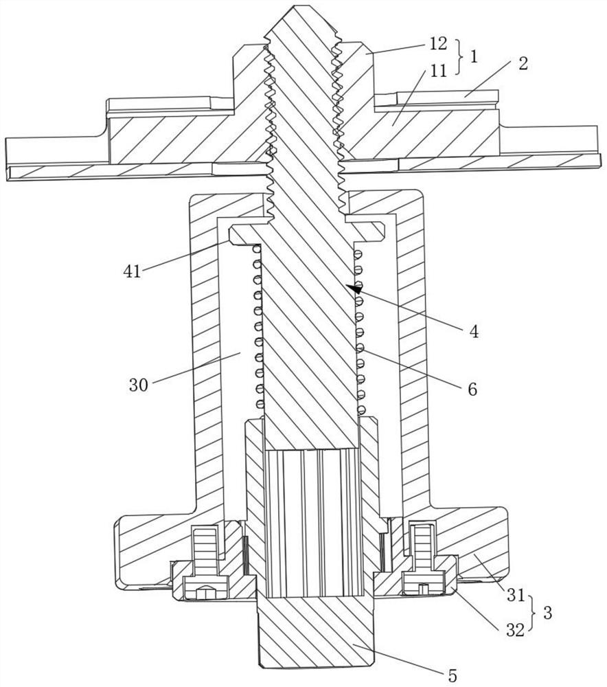
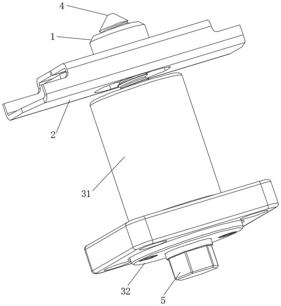
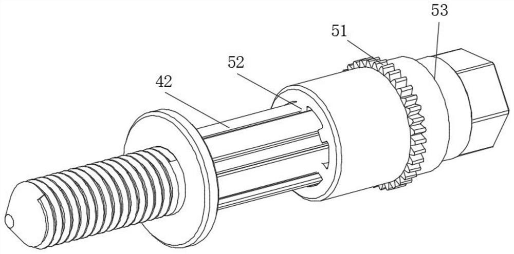
[0036] In order to make the technical problems solved by the present invention, the technical solutions adopted and the technical effects achieved clearer, the technical solutions of the present invention will be further described below in conjunction with the accompanying drawings and through specific implementation methods. It should be understood that the specific embodiments described here are only used to explain the present invention, but not to limit the present invention. In addition, it should be noted that, for the convenience of description, only the parts related to the present invention are shown in the drawings but not all of them.

[0037] In the description of the present invention, unless otherwise clearly specified and limited, the terms "connected", "connected" and "fixed" should be understood in a broad sense, for example, it can be a fixed connection, a detachable connection, or an integrated ; It can be a mechanical connection or an electrical connection;...


PUM


Abstract

The invention relates to the technical field of automobiles, and discloses a locking mechanism which comprises a nut assembly and a bolt assembly. The nut assembly comprises a nut and a fixing sleeve, and the nut can move relative to the fixing sleeve. The bolt assembly comprises a shell, a bolt and a transmission part, the bolt and the transmission part are arranged in the shell, and the bolt can abut against the nut so that the nut can move relative to the fixing sleeve and the bolt can move relative to the shell. The transmission part is arranged on the bolt in a sleeving mode, the shell is used for limiting rotation of the transmission part at the locking position, the transmission part can move in the axial direction of the bolt to leave the locking position, and the transmission part leaving the locking position can drive the bolt to rotate so that the bolt can be in threaded connection with the nut; an elastic piece is further included and arranged on the bolt in a sleeving mode, one end of the elastic piece abuts against a limiting protrusion on the bolt, and the other end of the elastic piece abuts against the transmission piece. In this way, the bolt abuts against the nut, the position of the nut is adjusted, then the nut and the bolt are in threaded connection through coaxial rotation of the transmission piece and the bolt, and high-precision rapid replacement of the battery pack is achieved.

Description

technical field [0001] The invention relates to the technical field of automobiles, in particular to a locking mechanism. Background technique [0002] With the development of my country's new energy electric vehicle technology, users have higher requirements for the cruising range and charging time of electric vehicles. However, due to the battery system and battery characteristics, it is currently impossible to charge in a short period of time to reach When the battery fast charging technology cannot be further improved due to the large cruising range, it becomes particularly important for electric vehicles to quickly replace the battery pack. [0003] At present, several locking mechanisms commonly used in battery pack replacement solutions mainly include snap-on, tension-on, and screw-on, but the above-mentioned locking mechanisms still have the following defects during use, for example, the snap-on locking mechanism wears out during use Larger, easy to get stuck, and re...

Claims


Application Information

Patent Timeline
Patent Type & Authority Applications(China)
IPC IPC(8): H01M50/262H01M50/249
CPCH01M50/262H01M50/249
Inventor 李扬李鸿键侯艳丽李玉军
Owner 北京胜能能源科技有限公司
Why Eureka
Try Eureka