
Multiphase boost conversion device

A boost conversion, boost converter technology, applied in output power conversion devices, DC power input to DC power output, instruments and other directions, can solve the problem of high conduction loss, 180-degree phase staggering, and large number of switching elements and other problems to achieve the effect of reducing the switching loss

Pending Publication Date: 2022-05-13
亚瑞源科技(深圳)有限公司 +2
View PDF0 Cites 0 Cited by
  • Summary
  • Abstract
  • Description
  • Claims
  • Application Information

AI Technical Summary

Problems solved by technology

[0004] However, some prior art dual-phase soft-switching boost converters have relatively high conduction losses and can only operate when the duty cycle is less than 50%. Some prior art dual-phase soft-switching boost converters The voltage converter cannot make the phase interleave 180 degrees when the duty cycle is less than 50%. In addition, the bi-phase soft-switching boost converter of some related technologies has too many switching elements.

Method used


Image

  • Multiphase boost conversion device
  • Multiphase boost conversion device
  • Multiphase boost conversion device

Examples


Embodiment Construction

[0014] Throughout this disclosure, numerous specific details are provided in order to provide a thorough understanding of specific embodiments of the invention; however, those skilled in the art will appreciate that without one or more of these specific details, the In other instances, well-known details are not shown or described in order to avoid obscuring essential technical features of the invention. Hereby, the technical content and detailed description of the present invention are described as follows in conjunction with the drawings:

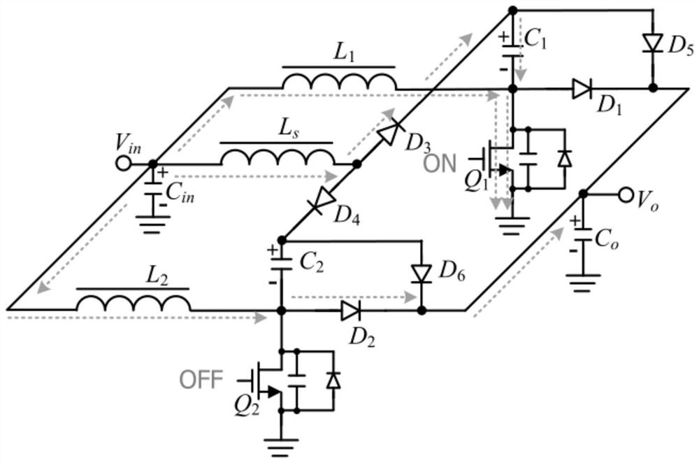
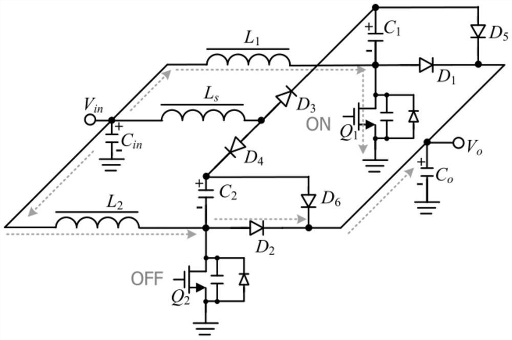
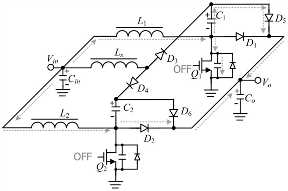
[0015] Please refer to image 3 , the multiphase boost conversion device 10 includes a multiphase boost converter 102 and a passive lossless buffer (buffer snubber, which can also be called a shock absorber) 104; the passive lossless buffer 104 includes a first resonance Capacitor C1, second resonance capacitor C2, first unidirectional conduction element D3 at the input end, second unidirectional conduction element D4 at the input end, f...


PUM


Abstract

A multiphase boost conversion device comprises a multiphase boost converter and a passive lossless buffer. The passive lossless buffer comprises a first resonance capacitor, a second resonance capacitor, an output end first one-way conduction element, an output end second one-way conduction element, an input end first one-way conduction element, an input end second one-way conduction element and a resonance inductor. The multi-phase boost converter has the advantages that the buffer with a simple structure is used for reducing switching loss of the multi-phase boost converter and reducing electromagnetic interference.

Description

technical field [0001] The invention is a multi-phase boost conversion device with a buffer, especially a multi-phase boost conversion device with a passive lossless buffer. Background technique [0002] The two-phase hard-switching boost converter will produce an obvious overlapping area of ​​voltage and current on the voltage and current waveform diagram when the switch is switched, and the overlapping area of ​​voltage and current is the switching loss of the switch. Losses reduce energy conversion efficiency and increase component temperature. [0003] Later, a two-phase soft-switching boost converter was proposed, which reduced the overlapping area of ​​the above-mentioned voltage and current, thereby reducing energy loss; Or the rising slope or falling slope of the switching current to reduce switching losses. [0004] However, some prior art dual-phase soft-switching boost converters have relatively high conduction losses and can only operate when the duty cycle is ...

Claims


Application Information

Patent Timeline
Patent Type & Authority Applications(China)
IPC IPC(8): H02M3/156H02M1/34H02M1/44
CPCH02M3/156H02M1/34H02M1/44
Inventor 洪宗良
Owner 亚瑞源科技(深圳)有限公司
Learn More