
Power detection circuit and terminal

A technology of power detection circuit and transmission power, which is applied in the field of communication, can solve the problems of increasing system layout space and waste of circuit resources, and achieve the effect of saving port resources and improving the utilization rate of circuit resources

Active Publication Date: 2022-05-13
VIVO MOBILE COMM CO LTD
View PDF12 Cites 2 Cited by
  • Summary
  • Abstract
  • Description
  • Claims
  • Application Information

AI Technical Summary

Problems solved by technology

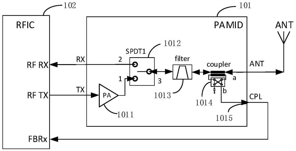
[0003] The purpose of this application is to provide a power detection circuit and terminal to solve the problem of waste of circuit resources caused by the configuration of separate feedback signal receiving paths in radio frequency time division duplex systems and radio frequency frequency division duplex systems and the problem of increasing the layout space of the system

Method used


Image

  • Power detection circuit and terminal
  • Power detection circuit and terminal
  • Power detection circuit and terminal

Examples


Embodiment Construction

[0061] Embodiments of the present invention will be described in detail below, examples of which are shown in the drawings, wherein the same or similar reference numerals denote the same or similar elements or elements having the same or similar functions throughout. The embodiments described below by referring to the figures are exemplary only for explaining the present invention and should not be construed as limiting the present invention. Based on the embodiments in this application, all other embodiments obtained by persons of ordinary skill in the art without creative efforts fall within the protection scope of this application.

[0062] The features of the terms "first" and "second" in the description and claims of the present application may explicitly or implicitly include one or more of these features. In the description of the present invention, unless otherwise specified, "plurality" means two or more. In addition, "and / or" in the specification and claims means at...


PUM


Abstract

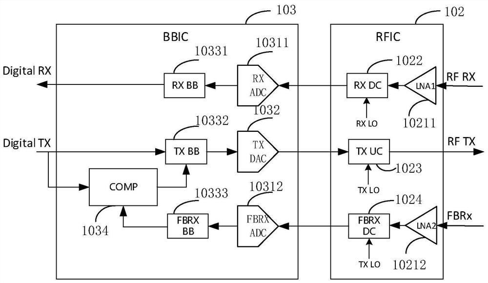
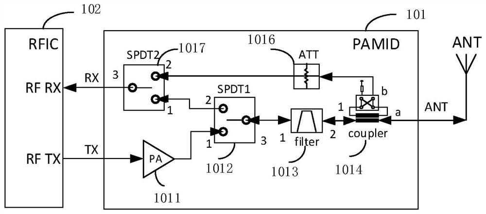
The invention discloses a power detection circuit, and belongs to the technical field of communication. The power detection circuit comprises a first radio frequency transceiver, a first power amplifier module, a first baseband signal processor and an antenna. The first radio frequency transceiver comprises a first signal down-conversion mixer, a first signal up-conversion mixer and a first low-noise amplifier. The first power amplifier module comprises a first power amplifier, a first single-pole double-throw switch, a first radio frequency filter, a first coupler, a second single-pole double-throw switch and a first attenuator; the first baseband signal processor comprises a first decoder, a first encoder, a first baseband signal processing unit, a second baseband signal processing unit, a first signal comparator and a third single-pole double-throw switch.

Description

technical field [0001] The application belongs to the technical field of communication, and in particular relates to a power detection circuit and a terminal. Background technique [0002] In the process of communicating with the base station, the terminal adjusts the power of the transmitted signal according to the strength of the received signal. To realize the automatic adjustment of the transmitted signal power of the terminal, the terminal needs to monitor its own transmitted signal power in real time. In order to realize the real-time feedback of the terminal transmission signal power, the radio frequency time division duplex system and the radio frequency frequency division duplex system are equipped with a special feedback signal receiving path, which increases the layout space of the radio frequency time division duplex system and radio frequency division duplex system, and The feedback signal receiving path cannot work in the RX time slot of the radio frequency tim...

Claims


Application Information

Patent Timeline
Patent Type & Authority Applications(China)
IPC IPC(8): H04B17/10
CPCH04B17/102Y02D30/70
Inventor 李天林
Owner VIVO MOBILE COMM CO LTD
Learn More