Bar sticking plate for slicing machine

A slicer and stick stick technology, which is applied in the manufacture of tools, fine working devices, working accessories, etc., can solve the problems of diamond wire wear, long cutting time of the knife, etc., to reduce the probability of wear, high cutting efficiency, and reduce production cost effect

Pending Publication Date: 2022-05-17
WUXI ZHONGHUAN APPLIED MATERIALS CO LTD
View PDF0 Cites 0 Cited by
  • Summary
  • Abstract
  • Description
  • Claims
  • Application Information

AI Technical Summary

Problems solved by technology

[0004] The invention provides a sticky stick plate for a slicer, which solves the technical problems of long cutting time and serious diamond wire wear in the prior art

Method used


Image

  • Bar sticking plate for slicing machine
  • Bar sticking plate for slicing machine
  • Bar sticking plate for slicing machine

Examples


Embodiment Construction

[0029] The present invention will be described in detail below in conjunction with the accompanying drawings and specific embodiments.

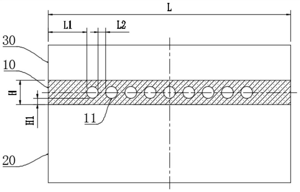
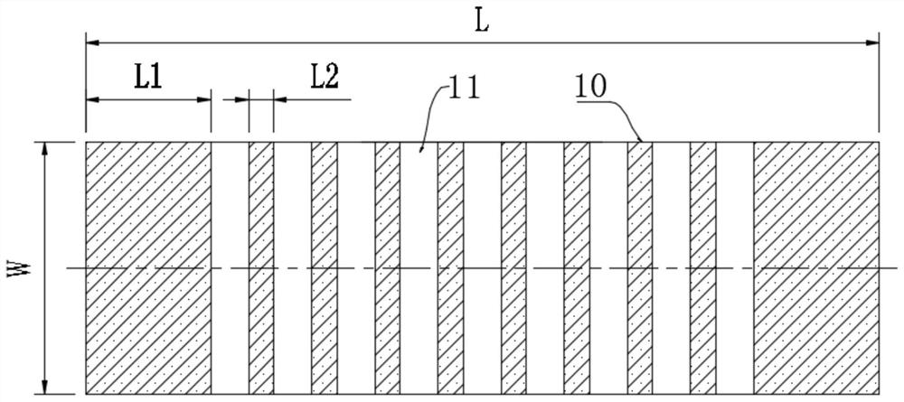
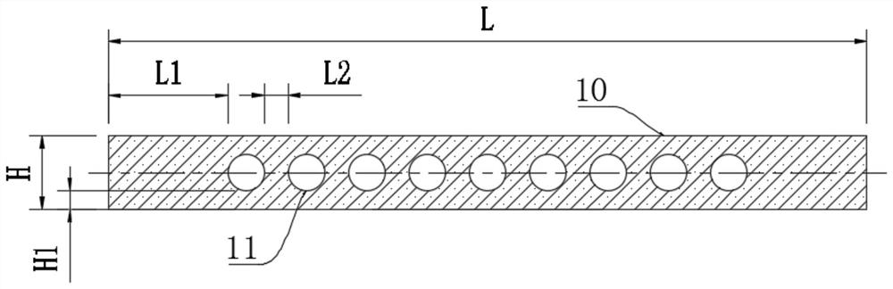
[0030] This embodiment proposes a sticky stick plate 10 for a slicer, and its matching structure with the silicon stick 20 and the material seat 30 is as follows: figure 1 As shown, in the slicer, a silicon rod 20 is bonded to one side of the sticky plate 10, and a material seat 30 is bonded to the other side opposite to the silicon rod 20, that is, the sticky plate 10 is bonded on the material seat 30 first. , and then bonded with the silicon rod 20, and then unifiedly installed in the installation compartment in the slicer after the final integral bonding, and make the side of the silicon rod 20 away from the sticking plate 10 face down and face the diamond wire The mesh is set, and the diamond wire mesh crosses the silicon rod 20 side by side and cuts the silicon rod 20 into several silicon wafers. In this embodiment, the sticky stick boa...


PUM


Abstract

According to the stick sticking plate for the slicing machine, a plurality of holes are formed in the stick sticking plate, and the holes are formed in the width direction of the stick sticking plate. According to the rod sticking plate, the bonding strength of the silicon rod and the slicing quality are not affected, meanwhile, the cutting time of a cutter can be shortened, the abrasion probability of a diamond wire is reduced, the production cost is reduced to the maximum extent, the rod sticking plate is irrelevant to the size and shape of the silicon rod, the universality is wide, and the cutting efficiency is high.

Description

technical field [0001] The invention belongs to the technical field of silicon wafer processing, and in particular relates to a sticky stick plate for a slicer. Background technique [0002] Before silicon wafer processing, silicon rods need to be bonded and placed on the sticky rod plate that has been bonded and fixed on the side of the material seat, and then the material seat is clamped to the wire cutting machine for cutting. Each batch of silicon rods cut Need to use a batch of sticky stick board, sticky sticky board can be reused, but can not be used for many times without limit, it is a high consumable part in the process of silicon wafer processing. Existing stick stick boards are all phenolic resin boards with solid structure, but this structure not only has high production cost, but also has relatively high hardness. At the end of silicon rod cutting, that is, when the knife is retracted, in order to cut through the silicon rod, the diamond wire will cut into the ...

Claims


Application Information

Patent Timeline
Patent Type & Authority Applications(China)
IPC IPC(8): B28D7/04B28D7/00
CPCB28D5/0082B28D5/0058
Inventor 孙钊
Owner WUXI ZHONGHUAN APPLIED MATERIALS CO LTD
Why Eureka
Try Eureka