Primary-secondary type logistics transfer system based on intelligent traffic service
A transportation service, mother-in-law technology, applied in the field of logistics, can solve the problems of inconvenient cargo handling, reduce labor, ensure stability, and improve work efficiency.
- Summary
- Abstract
- Description
- Claims
- Application Information
AI Technical Summary
Problems solved by technology
Method used
Image

Examples
Embodiment Construction
[0026] The following will clearly and completely describe the technical solutions in the embodiments of the present invention with reference to the accompanying drawings in the embodiments of the present invention. Obviously, the described embodiments are only some, not all, embodiments of the present invention.
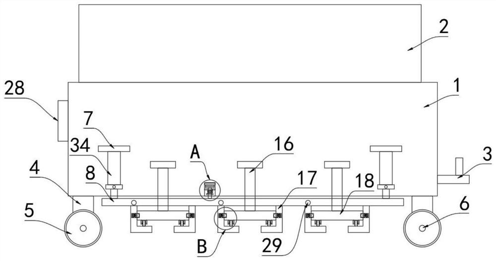
[0027] refer to Figure 1-4 , a mother-child logistics transfer system based on intelligent transportation services, including a transfer frame 1, a hook 3 is installed at one end of the transfer frame 1, a warehouse 2 is placed in the transfer frame 1, and a moving mechanism is installed at the bottom of the transfer frame 1 , the moving mechanism includes four support columns 4 fixedly connected to the bottom of the transfer frame 1, and the four support columns 4 are distributed in a rectangle. The front and rear ends of 6 are all equipped with wheels 5.
[0028] Two mounting blocks 7 are installed on the front side wall and the rear side wall of the transfer fra...
PUM
 Abstract
Description
Claims
Application Information
PatSnap Eureka turns technology decisions into work you can execute. Powered by our Innovation Knowledge Graph, it runs expert workflows across engineering, life sciences, materials and intellectual property. Get your review-ready output in minutes.


