Electronic protection switch

A technology of electronic protection and switching, applied to the power grid of electronic protection switches, operating this type of power grid field, can solve the problems of long service life of electronic switches, and achieve the effect of reliable positioning and high loss

Pending Publication Date: 2022-05-17
SIEMENS AG
View PDF1 Cites 0 Cited by
  • Summary
  • Abstract
  • Description
  • Claims
  • Application Information

AI Technical Summary

Problems solved by technology

This results in a long service life of the electronic switches

Method used


Image

  • Electronic protection switch
  • Electronic protection switch
  • Electronic protection switch

Examples


Embodiment Construction

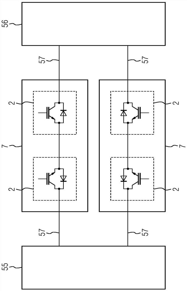
[0028] figure 1 A known arrangement is shown in which an energy source 55 is connected to a load 56 via two known electronic switches 7 . The electronic switches 7 are arranged here in the individual leads 57 electrically connecting the energy source 55 to the load 56 . In this case, for example, this is a DC voltage network in which the energy source 55 and the load 56 are connected to one another via two conductors 57 and in which a DC voltage is applied between the two conductors 57 . In order to be able to separate the load 56 from the energy supply network 55 , an electronic switch 7 is present in each of the two leads 57 . The current in only one of the two conductors 57 can be reliably switched off by means of the electronic switch 7 in the two conductors 57 , as can occur, for example, in the event of a ground fault.

[0029] The electronic switch 7 has a series connection of two semiconductor switches 2 arranged in series connection. In this case, the semiconductor...


PUM


Abstract

The invention relates to an electronic protection switch (1) having two semiconductor switches (2) of the same type, each of which has a switching element (21) and a diode (22) arranged antiparallel to the switching element (21). In order to improve the electronic switch, it is proposed that the electronic switch also has a first power supply connection (3) and a second power supply connection (4), each of which has a positive potential connection (31, 41) and a negative potential connection (32, 42), a first of the semiconductor switches (2) is arranged between a positive potential connection (31) of the first power supply connection (3) and a positive potential connection (41) of the second power supply connection (4) without a semiconductor series connection, a second of the semiconductor switches (2) is arranged between a negative potential connection (32) of the first power supply connection (3) and a negative potential connection (42) of the second power supply connection (4) without a semiconductor series connection, and the switching element (21) of the respective semiconductor switch (2) is arranged in such a way that the switching element (21) of the respective semiconductor switch (2) is connected to the first power supply connection (3) and the second power supply connection (4). A current from the first power supply interface (3) to the second power supply interface (4) can be conducted and switched off. The invention also relates to an electrical network (5), in particular a DC voltage network (6), having a first sub-network (51) and a second sub-network (52), the electrical network (5) having such an electronic protection switch (1) for disconnecting the first sub-network (51) and the second sub-network (52) from each other, the first sub-network (51) being connected to the first power supply interface (3) and the second sub-network (52) being connected to the second power supply interface (4). The invention also relates to a method for operating such an electrical network (5).

Description

technical field [0001] The invention relates to an electronic protective switch having two semiconductor switches each having a switching element and a diode arranged antiparallel to the switching element. Furthermore, the invention relates to a network having a first and a second subsystem and such an electronic protective switch for disconnecting the first subsystem from the second subsystem. The invention also relates to a method for operating a network of this type. Background technique [0002] Today, mechanical and electronic switches are used to switch electrical current. In the case of a mechanical switch, the contact between the two interfaces of the switch is mechanically made or broken. This applies in particular to the switching of alternating voltage currents, since they are inexpensive to manufacture and the switching operation can also be realized in a simple manner due to the zero crossing of the current. For the switching of direct current, the mechanical...

Claims


Application Information

Patent Timeline
Patent Type & Authority Applications(China)
IPC IPC(8): H03K17/082H02H3/32
CPCH03K17/0828H03K2217/0009H02H3/325H02H1/0007H02H3/16
Inventor 本诺·魏斯
Owner SIEMENS AG
Why Eureka
Try Eureka