Electronic system with heat transfer device

An electronic system and heat transfer technology, applied in electrical components, electrical equipment structural parts, cooling/ventilation/heating transformation, etc., can solve problems such as large structural space

Pending Publication Date: 2022-05-17
VOLKSWAGEN AG
View PDF2 Cites 0 Cited by
  • Summary
  • Abstract
  • Description
  • Claims
  • Application Information

AI Technical Summary

Problems solved by technology

However, this is associated with high costs and requires a relatively large construction space

Method used


Image

  • Electronic system with heat transfer device
  • Electronic system with heat transfer device
  • Electronic system with heat transfer device

Examples


Embodiment Construction

[0033] In order to better understand the principle of the present invention, the following describes the implementation of the present invention in more detail with reference to the accompanying drawings. It shall be understood that the invention is not limited to these embodiments and that the described features may also be combined or modified without departing from the scope of protection of the invention, as it is defined in the appended claims.

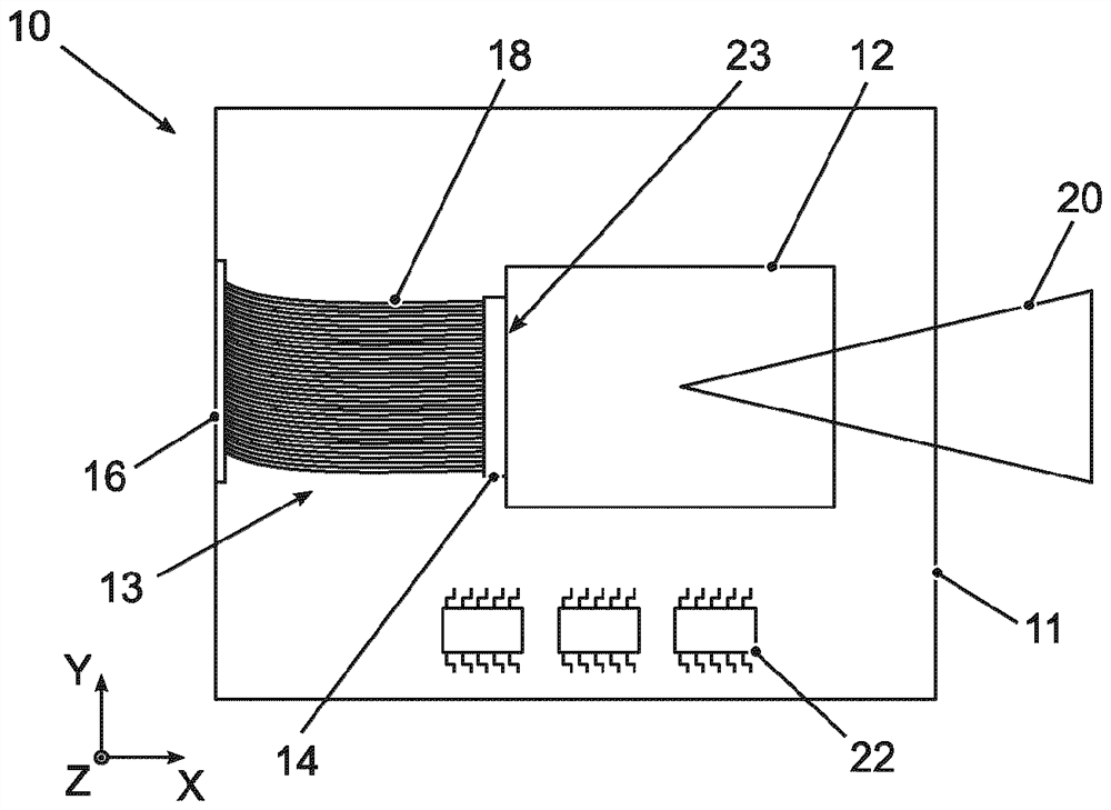
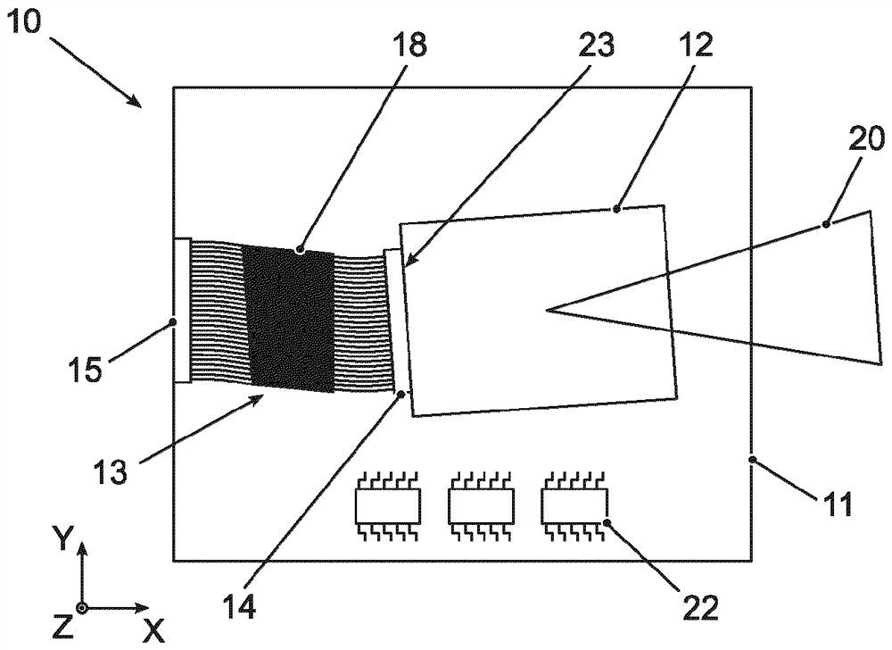
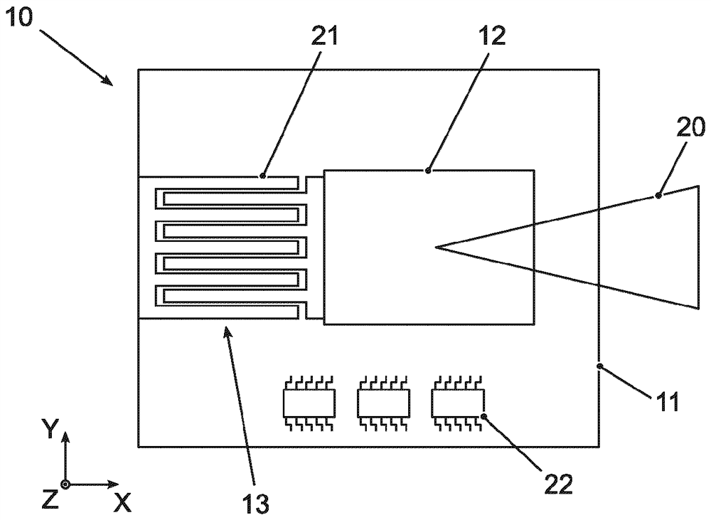
[0034] figure 1 A plan view of an electronic system 10 according to the prior art with a heat transfer device 13 is shown schematically. The electronic system 10 includes a housing 11 and electronic components 12 arranged in the housing 11 . In the example shown, the electronic component 12 is a sensor head of a lidar sensor. The sensor head has a detection cone 20 . Inside the housing 11 there is an internal electronics 22 which is to be protected against elevated temperatures. In order to transfer heat from the electronic c...


PUM


Abstract

The invention relates to an electronic system (10) having a heat transfer device (13). The invention also relates to a vehicle, in particular a motor vehicle, in which such an electronic system (10) is used. The electronic system (10) comprises a housing (11), an electronic component (12) arranged in the housing (11), and a heat transfer device (13) for transferring heat from the electronic component (12) to the housing (11). The heat transfer device (13) has at least one flexible comb-like or brush-like heat coupler (14, 15) for heat transfer by means of heat conduction.

Description

technical field [0001] The invention relates to an electronic system with a heat transfer device. The invention also relates to a vehicle, in particular a motor vehicle, in which such an electronic system is used. Background technique [0002] Many sensors are installed in today's motor vehicles, which are used, for example, for safety functions, assistance functions or cruise control functions. Examples of such sensors are radar sensors, lidar sensors, ultrasonic sensors or cameras. [0003] In high ambient temperatures, the sensor may have to be tuned or completely shut down in order to protect the internal electronics from overheating. As a result, it may occur that safety functions, assistance functions or cruise functions must be deactivated. To avoid this, the sensor must be cooled or the heat generated must be dissipated by suitable measures. [0004] In this regard, DE 11 2014 005 550 T5 describes a heat transfer device which couples a heat-generating element wit...

Claims


Application Information

Patent Timeline
Patent Type & Authority Applications(China)
IPC IPC(8): H05K7/20
CPCH05K7/20454
Inventor J·布乔尔斯基S·埃瓦尔德
Owner VOLKSWAGEN AG
Why Eureka
Try Eureka