

Electrically heatable coupling and an encased fluid hose with an electrically heatable coupling
a technology of electrically heatable coupling and fluid hose, which is applied in the direction of hose connection, machine/engine, pipe heating/cooling, etc., can solve the problems of urea not being supplied as intended, unable to meet the requirements of urea supply, etc., to achieve good heat conduction, increase the heat delivery to the opposing coupling, and good corrosion resistance
- Summary
- Abstract
- Description
- Claims
- Application Information
AI Technical Summary
Benefits of technology
Problems solved by technology
Method used
Image

Examples
Embodiment Construction
[0022] The following described illustrative embodiments of the invention with refinements should be regarded only as examples and should in no way limit the scope of protection of the patent claims. In the illustrative embodiments which are here described, the same reference numerals refer in the different figures to the same type of component. Not every component is therefore described in detail in illustrative embodiments.
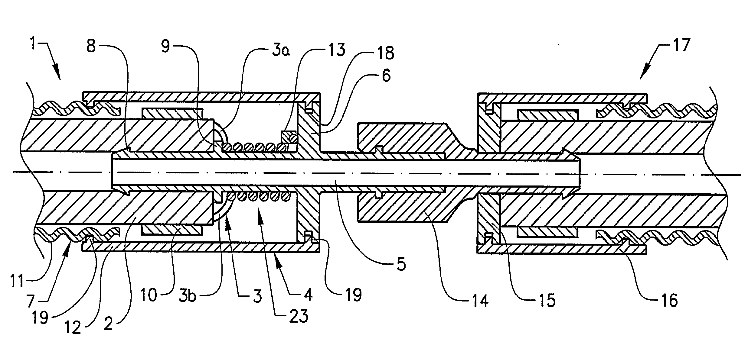
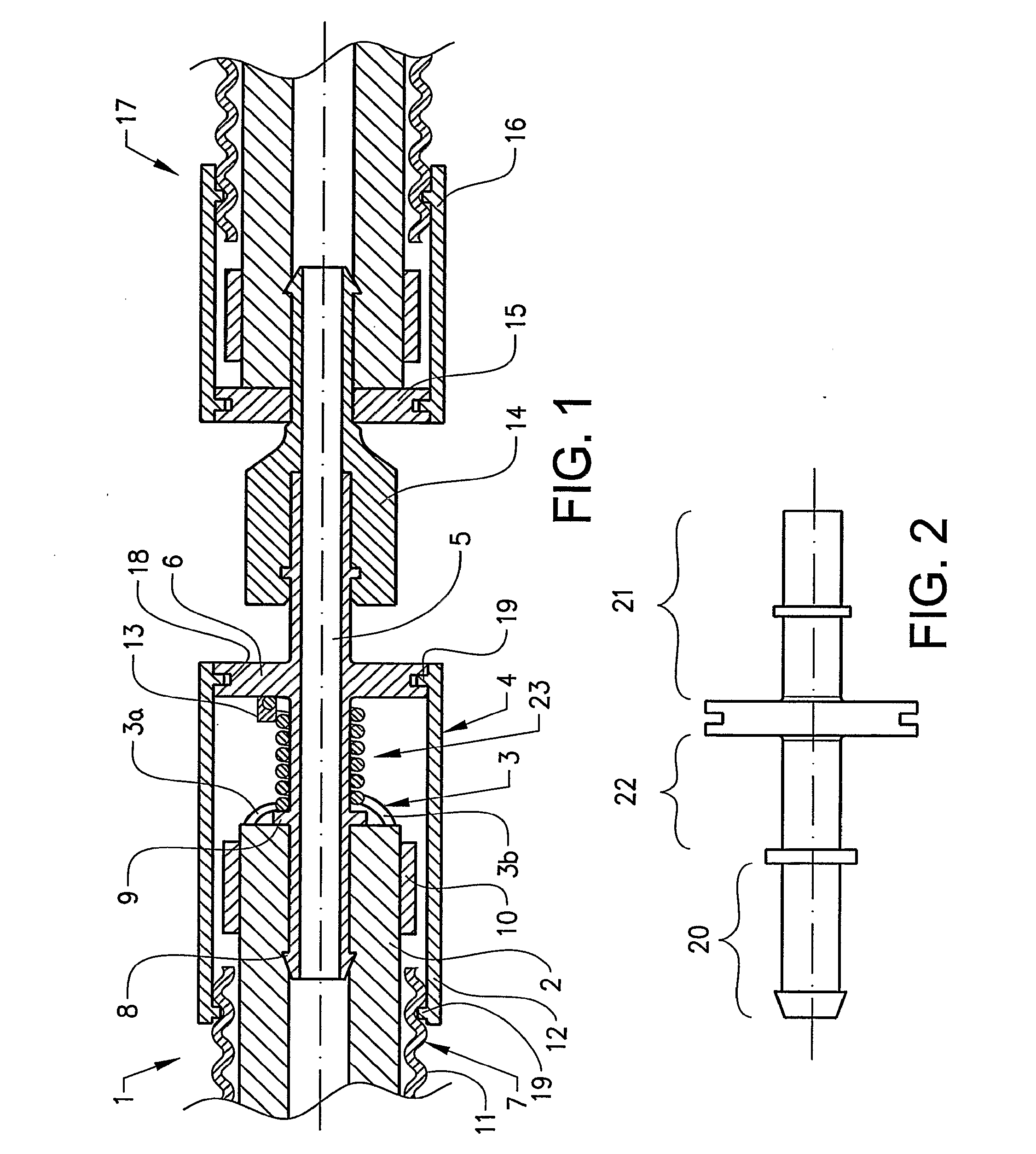
[0023]FIG. 1 shows a section of a heatable, encased fluid hose 1 with a coupling 5 according to the invention in cross section. The encased fluid hose 1 comprises a fluid hose 2, made of rubber, for example, with integrated heating cable 3 for heating of the hose 2. The hose 2 and the heating cable 3 are enclosed in a protective sheath 7. In this example, the heating cable 3 consists of two wires 3a, 3b, which are cast into the casing of the hose 2. The wires 3a and 3b are realized with a predefined resistivity, so that a defined heat generation is obtained when...
PUM
| Property | Measurement | Unit |
|---|---|---|
| thermal conductivity | aaaaa | aaaaa |
| electrically heatable | aaaaa | aaaaa |
| temperature | aaaaa | aaaaa |
Abstract
Description
Claims
Application Information