
Thermal Management Device For A Memory Module

a memory module and thermal management technology, applied in the direction of instruments, printed circuit aspects, basic electric elements, etc., can solve the problems of increasing the heat generated by the higher power chips over the others, generating more heat and creating a hot spot, and changing over tim

Inactive Publication Date: 2007-11-08
GRAFTECH INT HLDG INC
View PDF15 Cites 35 Cited by
  • Summary
  • Abstract
  • Description
  • Claims
  • Application Information

AI Technical Summary

Benefits of technology

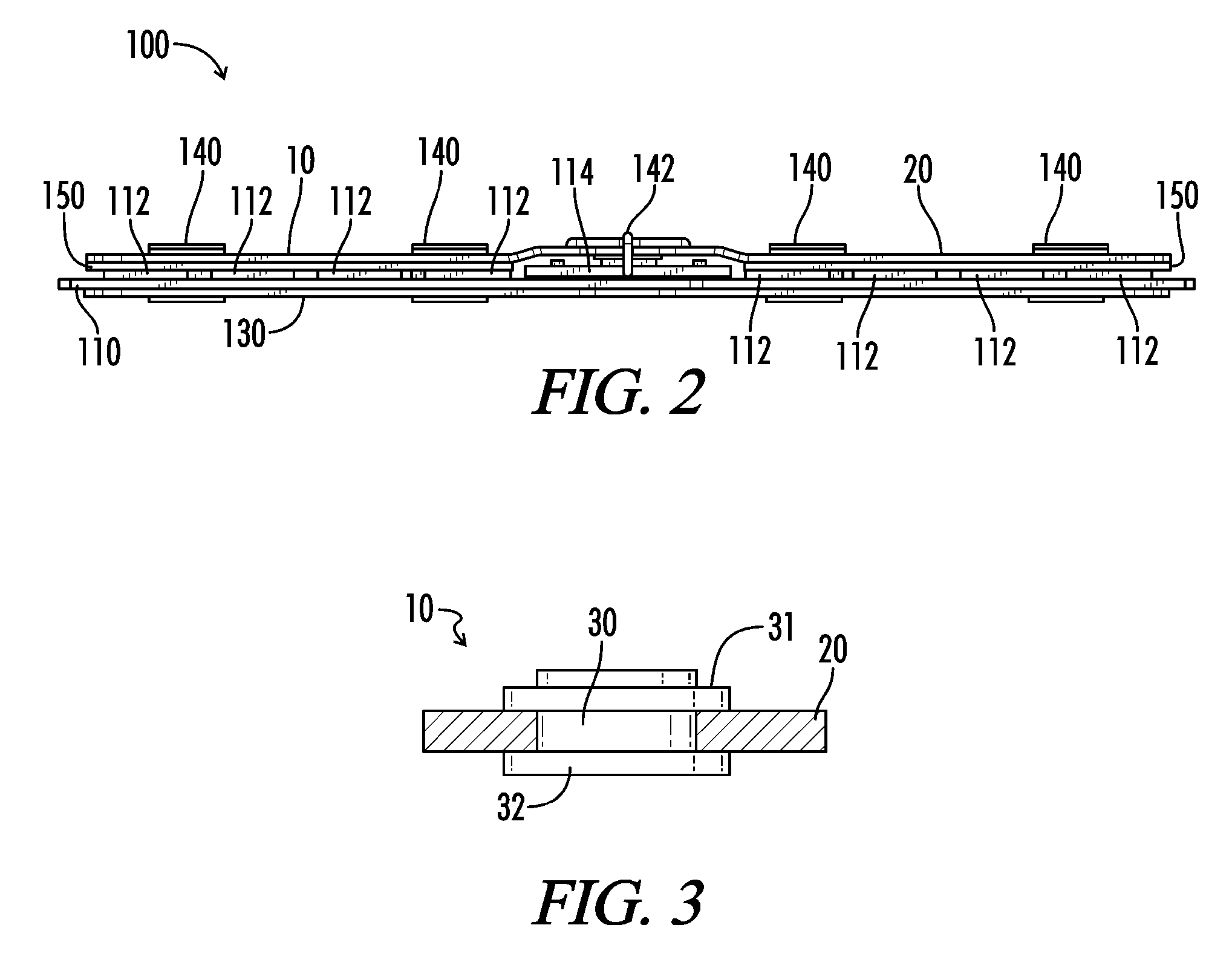
[0022] Yet another object of the invention is to provide a graphite-based heat spreader having a via therein to improve thermal transfer into the spreader.
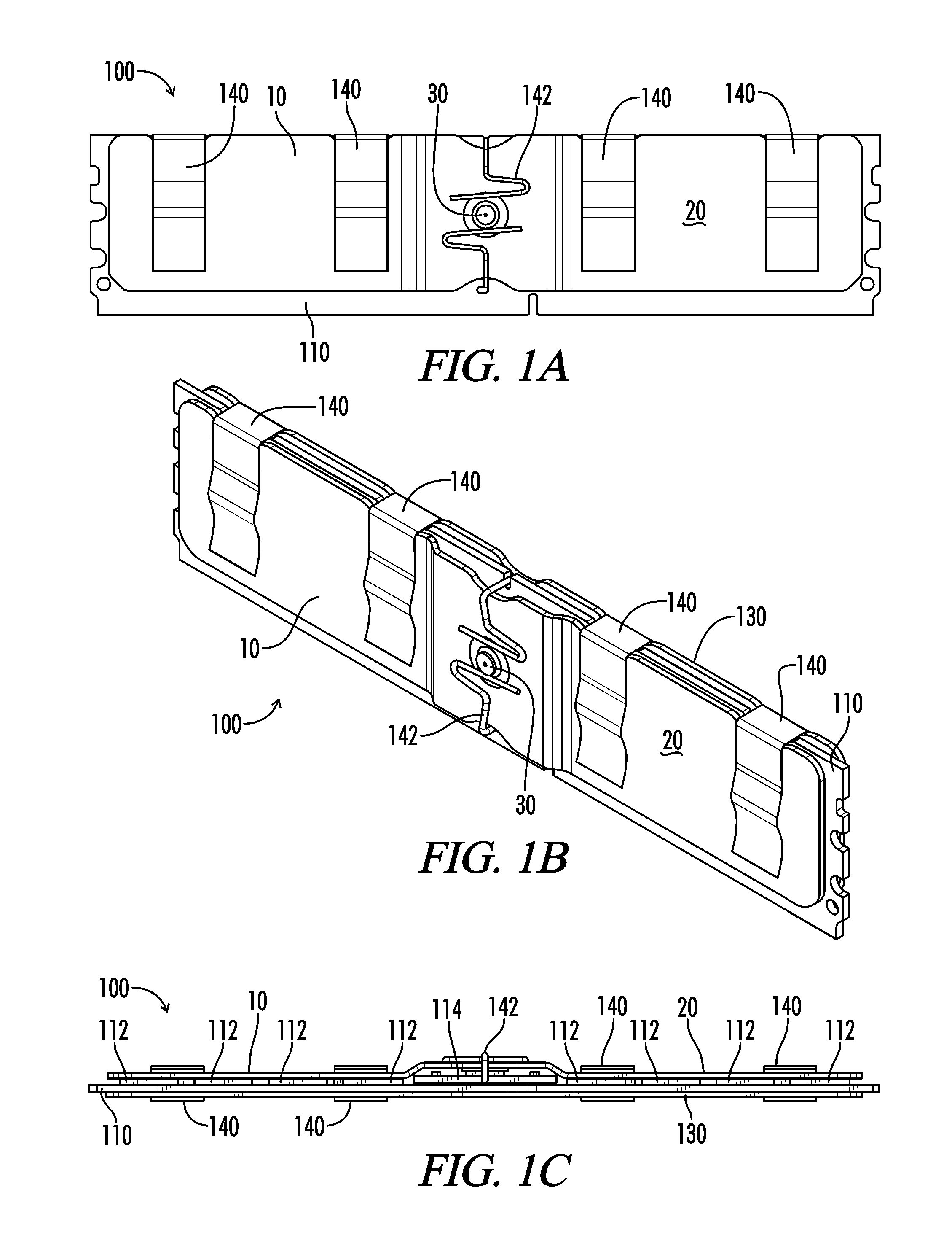
[0025] In addition, the inventive memory module can further comprise a heat spreader in thermal contact with the major surface of the memory board other than the surface on which are the chips. Also a rigidifying material can maintain the profile of the thermal management system, and a thermal interface material can be positioned between the thermal management system and the memory board.

Problems solved by technology

Certain of these chips may operate at higher power than others of the chips, resulting in more heat generated by the higher power chips than the others.
These hot spots are disadvantageous, since they can have a negative effect on operation of the memory module or adjacent electronic components.
Moreover, during operation of the device containing the memory module, which chip(s) are operating at higher power and, therefore, generating more heat and creating a hot spot, can change over time.
In addition, the AMB chip generally extends higher from the board than other chips (or, in the parlance, is taller than other chips on the board), resulting in an irregular contour for the FB-DIMM, making placement of conventional, flat thermal management devices impractical.
Other memory modules such as registered DIMMs (RDIMMs), which buffer data and reduce system loading to enable high density, highly reliable memory systems, also present equivalent heat management issues.
In addition to heat management for memory modules causing difficulties per se, those difficulties are exacerbated when it is desired that certain international standards governing module thickness, etc., be met.
Conventional heat spreaders for memory modules cannot effectively dissipate the amount of heat required while being thin enough to meet some such standards.
However DIMM pitch can often be problematic since tighter spacing results in reduced airflow; thus, a thinner spreader than conventional enables more airflow for given DIMM spacing.

Method used


Image

  • Thermal Management Device For A Memory Module
  • Thermal Management Device For A Memory Module
  • Thermal Management Device For A Memory Module

Examples


Embodiment Construction

[0032] Graphite is a crystalline form of carbon comprising atoms covalently bonded in flat layered planes with weaker bonds between the planes. By treating particles of graphite, such as natural graphite flake, with an intercalant of, e.g. a solution of sulfuric and nitric acid, the crystal structure of the graphite reacts to form a compound of graphite and the intercalant. The treated particles of graphite are hereafter referred to as “particles of intercalated graphite.” Upon exposure to high temperature, the intercalant within the graphite decomposes and volatilizes, causing the particles of intercalated graphite to expand in dimension as much as about 80 or more times its original volume in an accordion-like fashion in the “c” direction, i.e. in the direction perpendicular to the crystalline planes of the graphite. The exfoliated graphite particles are vermiform in appearance, and are therefore commonly referred to as worms. The worms may be compressed together into flexible she...


PUM


Abstract

A memory module which includes a memory board having two major surfaces, one of the major surfaces with a plurality of chips thereon, wherein at least one of the chips operates at a higher power than at least one other of the chips; and a thermal management system in thermal contact with one or more of the chips which operate at a higher power than at least one other of the chips, wherein the thermal management system spreads heat generated by the one or more of the chips which operate at a higher power than at least one other of the chips with which the thermal management system is in contact.

Description

RELATED APPLICATION [0001] This application claims priority under 35 U.S.C. §119 from Provisional U.S. Patent Application having Ser. No. 60 / 797,098, entitled “Thermal Management Device For A Memory Module,” filed May 3, 2006, the disclosure of which is incorporated herein by reference.TECHNICAL FIELD [0002] The present invention relates to a device or apparatus for thermal management for a memory module, as well as a memory module exhibiting improved thermal properties. More particularly, the inventive device functions to reduce hot spot temperatures resulting from various operating parameters of the memory modules BACKGROUND OF THE ART [0003] Memory modules (sometimes referred to as dual inline memory modules or DIMMs) used in computers, servers, and workstations, conventionally include a plurality of memory chips (DRAMs) and other components positioned on a printed circuit board and can include integrated control chips such as registers or advanced memory buffers (AMBs). Historic...

Claims


Application Information

Patent Timeline
IPC IPC(8): H01L23/34
CPCH01L23/34H05K1/0204H05K2201/0323H01L2924/0002H01L2924/00G06F1/20
Inventor REIS, BRADLEY E.REYNOLDS, ROBERT A. IIISMALE, MARTIN DAVIDKRAMER, GREGORYCAPP, JOSEPH PAUL
Owner GRAFTECH INT HLDG INC
Learn More