Differential electromagnetic type vibration energy collection device
An electromagnetic vibration and energy harvesting technology, applied in electromechanical devices, reciprocating/swinging/vibrating magnetic circuit components, magnetic circuit shape/style/structure, etc., to achieve the effects of increased speed, ingenious device structure, and simple design
- Summary
- Abstract
- Description
- Claims
- Application Information
AI Technical Summary
Problems solved by technology
Method used
Image
Examples
Embodiment 1
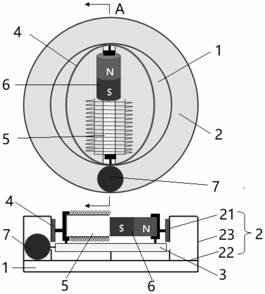
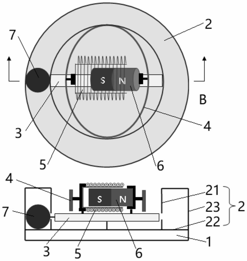
[0034] combine Figure 1~2 As shown, the present invention provides a differential electromagnetic vibration energy harvesting device, comprising a base plate 1, an annular chute 2 fixedly arranged on the upper surface of the base plate 1, a bar-shaped limiting groove 3 movably arranged on the upper surface of the base plate 1, a fixed The elliptical track 4 which is arranged above the bottom plate 1 and whose central axis coincides with the central axis of the annular chute 2, the electromagnetic energy conversion device which is movably arranged in the strip-shaped limiting groove 3, and which is movably arranged in the annular chute Roller Ball 7 within 2. Wherein, the annular chute 2 includes an inner ring side wall 21, a bottom wall 22 and an outer ring side wall 23, the strip-shaped limiting groove 3 is located in the area enclosed by the inner ring side wall 21, and the bar-shaped The length of the limiting groove 3 is not greater than the diameter of the inner ring of...
Embodiment 2
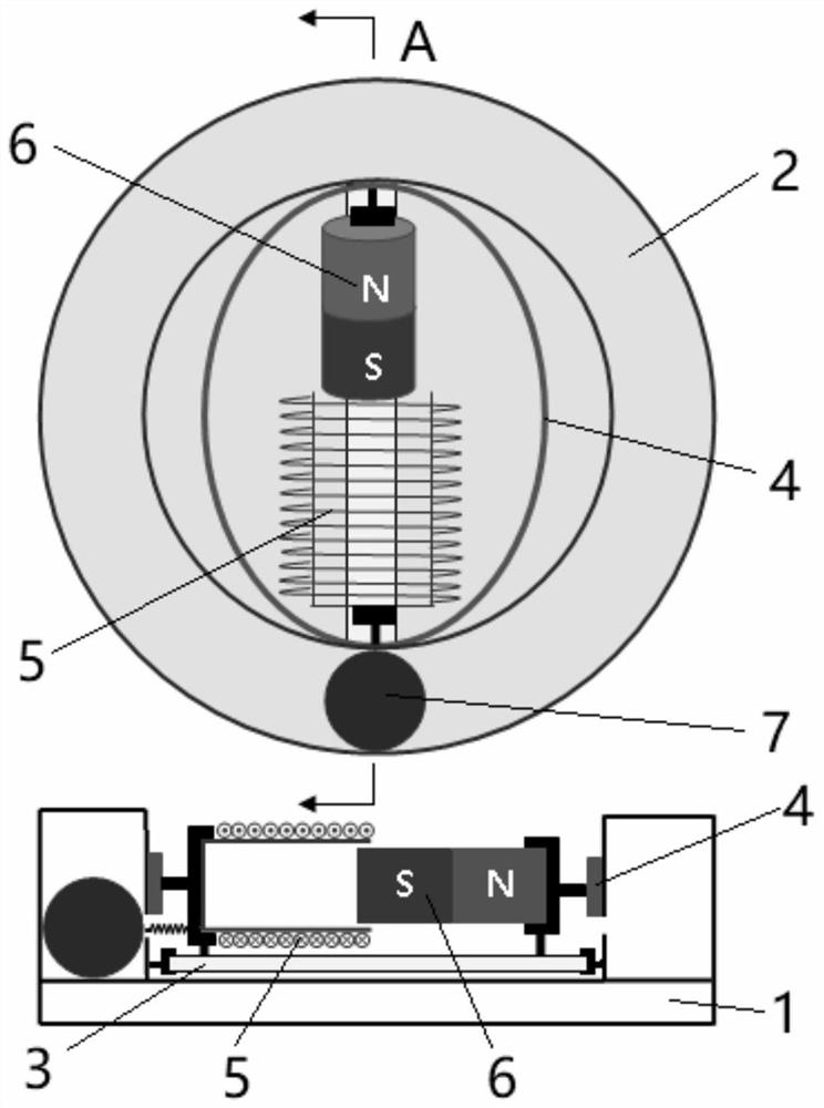
[0037] combine Figure 3~4 As shown, the structure of this embodiment is basically similar to that of Embodiment 1, the difference is that the two ends of the strip-shaped limiting groove 3 are respectively provided with first connecting pieces, and the inner ring side wall 21 of the annular chute 2 A first annular groove is provided in the outer circumferential direction, and a first connecting piece is movably arranged in the first annular groove, and the first connecting piece is a sliding connecting piece; the rolling ball 7 is connected with the sliding connecting end of the coil 5 .
[0038] When in use, place the lower surface of the base plate 1 on a vibration source, and when the base plate 1 is vibrated in multiple directions, the rolling ball 7 will roll in the annular chute 2, and the coil 5 will therefore Received a traction force, the coil 5 transmits the traction force to the strip-shaped limiting groove 3 where it is located, so that the connecting piece of the...
Embodiment 3
[0040] combine Figure 5~6 As shown, the structure of this embodiment is basically similar to that of Embodiment 1, the difference is that the strip-shaped limiting groove 3 is fixedly arranged on the bottom plate 1, and the elliptical track 4 is movably arranged above the bottom plate 1 , the rolling ball 7 is connected to one end of the elliptical track 4, the top of the inner ring side wall 21 of the annular chute 2 is provided with a second annular groove, and the bottom of the elliptical track 4 is provided with two second connecting The second connecting piece is movably connected in the second annular groove, and the second connecting piece is a rolling connecting piece.
[0041] When in use, the lower surface of the bottom plate 1 is placed on a vibration source. When the bottom plate 1 is vibrated in multiple directions, the rolling ball 7 will roll in the annular chute 2, thereby driving the elliptical The track 4 rotates around the central axis of the annular chute...
PUM
 Abstract
Description
Claims
Application Information
 - R&D
- Intellectual Property
- Life Sciences
- Materials
- Tech Scout
- Unparalleled Data Quality
- Higher Quality Content
- 60% Fewer Hallucinations
Browse by: Latest US Patents, China's latest patents, Technical Efficacy Thesaurus, Application Domain, Technology Topic, Popular Technical Reports.
© 2025 PatSnap. All rights reserved.Legal|Privacy policy|Modern Slavery Act Transparency Statement|Sitemap|About US| Contact US: help@patsnap.com


