Reusable fixed tissue holder

A technology of paper towel holder and rod holder, which is applied in the field of reusable and fixed paper towel holder, which can solve the problems that the paper towel holder cannot be effectively carried, the size of the suction cup cannot be too small, and it is not very easy to remove, so as to achieve adsorption and fixation, save time and effort, and solve the problem of Easy to be knocked down, easy to fix the effect

Pending Publication Date: 2022-05-24
桐乡市蜗殒供应链管理有限公司
View PDF11 Cites 0 Cited by
  • Summary
  • Abstract
  • Description
  • Claims
  • Application Information

AI Technical Summary

Problems solved by technology

However, since the paper towel holder needs better adsorption force, the size of the general suction cup should not be too small, otherwise the paper towel holder cannot be effectively carried
In the extrusion process, first, it takes a certain amount of effort, and may be repeatedly squeezed to fix the paper towel holder; second, the extrusion force used for fixing different sizes of suction cups is different; and the other is to remove the fixed paper towel holder , it is not very easy to remove due to the suction cup adsorption force

Method used


Image

  • Reusable fixed tissue holder
  • Reusable fixed tissue holder
  • Reusable fixed tissue holder

Examples


Embodiment 1

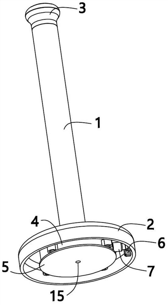
[0038] see Figure 1 to Figure 3 , the present invention provides a kind of technical scheme:

[0039] A reusable fixed tissue holder comprising:

[0040] A rod frame, including a first rod frame 1 and a second rod frame 3 sleeved on the first rod frame 1;

[0041] The base 2 is fixed with one end of the first rod frame 1;

[0042] The disk seat 4 is installed in the base 2;

[0043]The suction cup body 5 is installed on the disc base 4;

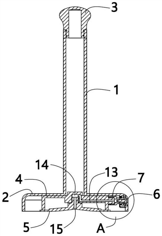
[0044] A first channel 13 is opened on the disk base 4, and a second channel 15 connected to the channel 13 is provided on the suction cup body 5;

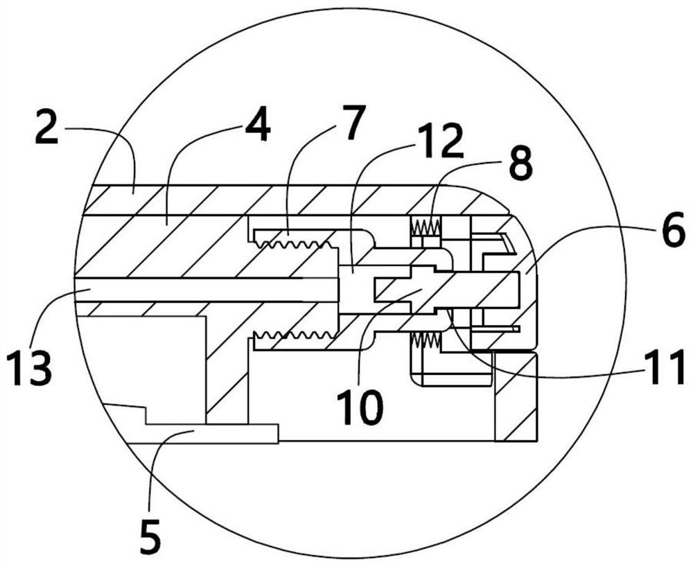
[0045] The button structure is installed on the base 2 and is used to realize the communication between the first channel 13 and the second channel 15 and the outside atmosphere.

[0046] Specifically, when the suction cup body 5 is adsorbed on the smooth surface, a structure for discharging the gas between the suction cup body 5 and the smooth surface is also included.

[0047] Specifical...

Embodiment 2

[0054] see Figure 4 As shown, the structure is basically the same as that of Embodiment 1, and the difference is:

[0055] The structure includes an open tube 19 and a rubber stopper 20 matched with the tube 19. The tube 19 and the second channel 15 communicate with each other through a pipeline 25. The pipeline 25 is provided with a one-way valve 26. By pressing The second rod frame 3 generates a negative pressure between the suction cup body 5 and the smooth surface so that the tube 19 passes through the second channel 15 . The first rod frame 1 is hollow inside, the second rod frame 3 is movably inserted into the first rod frame 1, the tube 19 is installed in the first rod frame 1, and the second rod frame 3 is linked by linkage mechanism to generate negative pressure in the tube 19. The linkage mechanism includes a first rack 16 , a second rack 17 and a gear 18 . One end of the first rack 16 is connected to the bottom end of the second rod frame 3 , and the other end is...

Embodiment 3

[0062] see Image 6 As shown, the structure is basically the same as that of Embodiment 2, and the difference is:

[0063] The bottom end of the second rod frame 3 is connected with a push rod 31, the bottom end of the push rod 31 is connected with the top end of the tube 19, the first rod frame 1 is hollow, and the tube 19 is installed on the first rod frame 19. In a rod frame 1 , one end of a support rod 29 with a chute 32 is connected to the rubber plug 20 , and the other end is fixed to the inner wall of the first rod frame 1 .

[0064] Specifically, the upper and lower ends of the support rod 29 are provided with through holes 30 connected to the shaft 32, the through hole 30 at the upper end is located in the tube 19, the through hole 30 at the lower end is connected with the pipe 25, the support rod The bottom of 29 is reserved with a vent hole which is connected with the tunnel 32, and one end of the plug cover 24 penetrates the first rod frame 1 to block the vent hol...


PUM


Abstract

The invention relates to the technical field of furniture supplies, in particular to a reusable fixed tissue holder, which comprises a rod frame, a first rod frame and a second rod frame, and the first rod frame is sleeved with the second rod frame; the base is fixed with one end of the first rod frame; the disc seat is mounted in the base; the sucking disc body is mounted on the disc seat; a first channel is formed in the sucker seat, and a second channel connected with the first channel is formed in the sucker body; the button structure is installed on the base and used for enabling the first channel and the second channel to be communicated with the outside atmosphere. According to the tissue holder, the pipe barrel is used for exhausting air in the cavity to form negative pressure, the negative pressure can be rapidly achieved between the suction cup body and the wall face and the wall face needing to be adsorbed and fixed, and therefore the tissue holder can be adsorbed to the wall face and the wall face without too large pressing force.

Description

technical field [0001] The invention relates to the technical field of furniture articles, in particular to a reusable fixed tissue holder. Background technique [0002] Rolled toilet paper and paper towels are commonly used items in our lives. The paper towel holder is made of plastic or metal material, and a shaft is set on the base. The middle round hole of the rolled paper towel is set on the shaft, and the roll paper or origami is built or placed It is used in private and public places such as home, hotels, bathrooms, toilets, public places, entertainment places, etc. When using, the tissue holder is usually fixed with bolt locks or double-sided tapes, and then the paper roll sleeve is used. , the next section must be torn off when taking it. However, these two fixing methods will limit the use of the paper towel holder, and cannot be properly changed according to the needs of use. Once the paper towel holder is removed from its original position, it will inevitably be...

Claims


Application Information

Patent Timeline
Patent Type & Authority Applications(China)
IPC IPC(8): A47K10/22
CPCA47K10/22A47K10/3836A47K2010/3863
Inventor 吕翔宇
Owner 桐乡市蜗殒供应链管理有限公司
Why Eureka
Try Eureka