Pig feed biological additive processing device
A technology of biological additives and processing equipment, applied in feed, food processing, grain processing, etc., can solve the problems of unfavorable discharge and slow discharge speed, and achieve the effect of strong practicability, large screening area and improved screening effect
- Summary
- Abstract
- Description
- Claims
- Application Information
AI Technical Summary
Problems solved by technology
Method used
Image


Examples
Embodiment 1
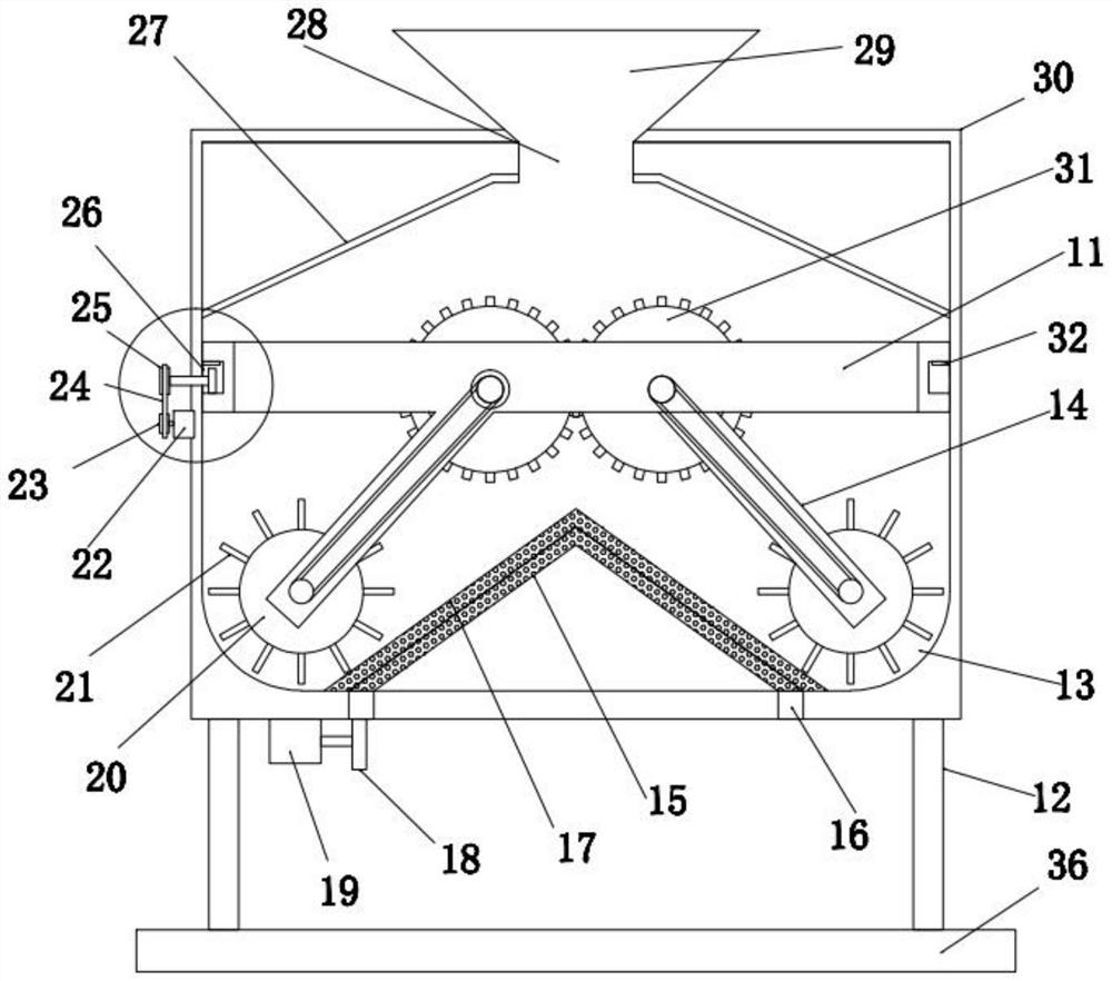
[0024] as Figure 1-Figure 4 As shown, a pig feed biological additive processing apparatus, comprising a base 36 and a crushing box 30 disposed above it, the lower end of the crushing box 30 is fixed by connecting with the base 36 through the outrigger 12, the crushing box 30 is provided with a feeding port 28 in the middle position of the upper end, the lower feeding port 28 is provided with a feeding hopper 29, the feeding hopper 29 is provided with a crushing component for crushing the biological additive, the crushing box 30 is provided with an outlet in the middle of the lower end, Outlet position is equipped with a filter assembly for filtering the material, the filter assembly is a conical filtration structure, effectively stacking the unqualified materials around, to avoid the impact of the return material on the discharge, the actual use, the material is added along the hopper 29, under the action of the crushing assembly, the material will be quickly crushed, the crushed ...
Embodiment 2
[0035] See Figure 5-6 , different from Example 1 is: the rotating ring 16 and the lower end of the first filter 15 are placed on the movable base 42, the active base 42 and the shredding box 30 at the bottom of the placement hole 40 between the gap, the upper end of the gap is connected by an elastic connection block 41, the active base 42 lower end array distribution has several buffer rods 39, the buffer rod 39 lower end sliding sleeve is provided with a buffer sleeve 38, the outer side of the buffer sleeve 38 is fixed by the positioning rod and the outrigger 12 connection, The limit block at the lower end of the buffer rod 39 is fixed by means of a reciprocating spring 37 connection between the lower end of the buffer sleeve 38, the second filter 17 is distributed on the surface of a raised ring 43 corresponding to the end of the dial plate 21, and the push force on the raised ring 43 is intermittently generated when the dial plate 21 rotates, so that the active base 42 slides ...
PUM
 Abstract
Description
Claims
Application Information