Intelligent loading and stacking device
A palletizing device and intelligent technology, applied in the field of palletizing, can solve the problems of reduced loading space, collision, and reduced loading capacity, and achieve the effect of avoiding shaking and collision
- Summary
- Abstract
- Description
- Claims
- Application Information
AI Technical Summary
Problems solved by technology
Method used
Image
Examples
Embodiment 1
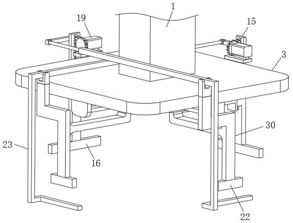
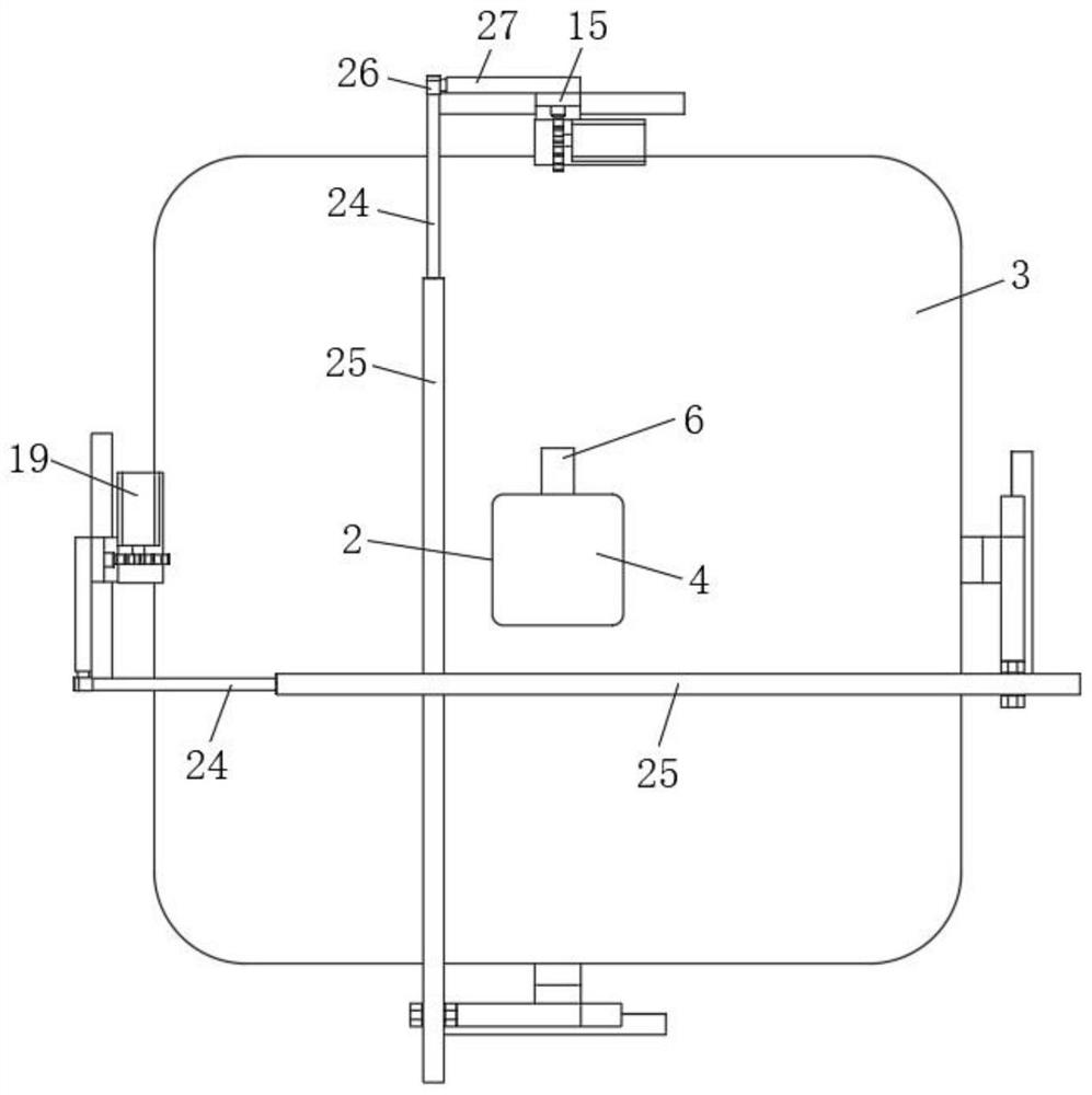
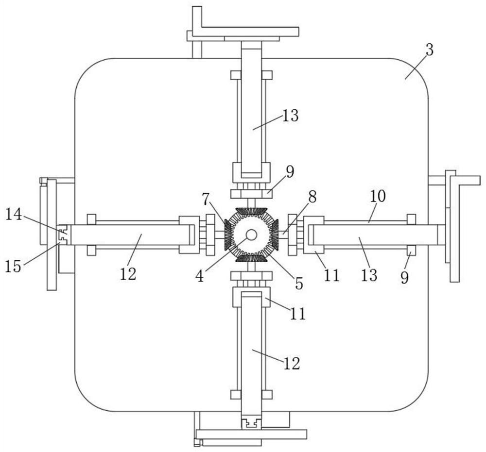
[0034] like Figure 1 to Figure 6 As shown, an intelligent loading and palletizing device includes a mounting plate 3, a clamping device 30 and a mechanical arm 1. A driving device 2 is fixedly mounted on the mounting plate 3, and the clamping device 30 is used to clamp the cartons. The clamping device 30 is connected to the driving device 2 , and the mechanical arm 1 is fixed to the mounting plate 3 for handling and stacking the mounting plate 3 .
[0035] The drive device 2 includes a drive motor 4, the output end of the drive motor 4 rotates through the mounting plate 3, and the end is fixed with a first bevel tooth 5, and the drive motor 4 and the mounting plate 3 are fixed by a connecting piece 6. , the mechanical arm 1 is sleeved on the outside of the drive motor 4 and fixed with the mounting plate 3, the first bevel teeth 5 are meshed with four second bevel teeth 7, and the four second bevel teeth 7 are equally spaced. , a screw rod 8 is fixedly installed on the second...
Embodiment 2
[0039] like Figure 1 to Figure 6 As shown, this embodiment is basically the same as the first embodiment. Preferably, a sliding plate 14 is fixedly installed at the end of the first connecting rod 12, and a first clamping plate 15 is slidably inserted into the sliding plate 14. A clamping plate 15 is T-shaped, the middle of the first clamping plate 15 is slidably connected with the slide plate 14 , the bottom of the lower end of the first clamping plate 15 is fixed with the first clamping jaw 16 , and the end of the second connecting rod 13 is The second clamping plate 21 is fixedly installed at the bottom, and the second clamping jaw 22 at the bottom end of the second clamping plate 21 is fixed;
[0040] A rack 17 is fixed on the inner side of the upper end of the first clamping plate 15 , a support plate 18 is fixed on the top of the sliding plate 14 , a lift motor 19 is fixed on the support plate 18 , and a lift gear is fixed at the output end of the lift motor 19 20, the...
Embodiment 3
[0043] like Figure 1 to Figure 6As shown, this embodiment is basically the same as the first embodiment. Preferably, a pushing device 23 is installed between the top end of the first clamping plate 15 and the second clamping plate 21, and the pushing device 23 includes a telescopic rod 24 and an installation post 25, the telescopic rod 24 is slidably inserted into the installation post 25, the top of the telescopic rod 24 is fixedly equipped with a connecting head 26, and the connecting head 26 is rotatably connected with a connecting post 27, the connecting post 27 is fixed to the back of the second clamping plate 21, the mounting post 25 is L-shaped, and a support block 28 is rotatably connected at the corner, the supporting block 28 is fixed to the second clamping plate 21, and the mounting post 25 is another One end is fixedly equipped with a push rod 29, wherein, when the first clamping plate 15 drives the first clamping jaw 16 to move horizontally to perform clamping wo...
PUM
 Abstract
Description
Claims
Application Information
 - R&D
- Intellectual Property
- Life Sciences
- Materials
- Tech Scout
- Unparalleled Data Quality
- Higher Quality Content
- 60% Fewer Hallucinations
Browse by: Latest US Patents, China's latest patents, Technical Efficacy Thesaurus, Application Domain, Technology Topic, Popular Technical Reports.
© 2025 PatSnap. All rights reserved.Legal|Privacy policy|Modern Slavery Act Transparency Statement|Sitemap|About US| Contact US: help@patsnap.com


