
Galvanometer positioning tool and laser printer

A technology for positioning tooling and positioning components, which is applied in the direction of optics, optical components, and improvement of process efficiency. It can solve the problems affecting the accuracy and accuracy of the output image and the position of the laser beam, so as to ensure the accuracy and precision. Effect

Pending Publication Date: 2022-05-24
佛山市顺德区蚬华多媒体制品有限公司 +1
View PDF0 Cites 0 Cited by
  • Summary
  • Abstract
  • Description
  • Claims
  • Application Information

AI Technical Summary

Problems solved by technology

Therefore, the installation orientation of the galvanometer greatly affects the marking position of the laser beam on the photosensitive drum, thereby affecting the accuracy and accuracy of the final output image

Method used


Image

  • Galvanometer positioning tool and laser printer
  • Galvanometer positioning tool and laser printer
  • Galvanometer positioning tool and laser printer

Examples


Embodiment Construction

[0031] In order to make the above objects, features and advantages of the present invention more clearly understood, the specific embodiments of the present invention will be described in detail below with reference to the accompanying drawings. In the following description, numerous specific details are set forth in order to provide a thorough understanding of the present invention. However, the present invention can be implemented in many other ways different from those described herein, and those skilled in the art can make similar improvements without departing from the connotation of the present invention. Therefore, the present invention is not limited by the specific embodiments disclosed below.

[0032] A galvanometer positioning tool 100 and a laser printer provided by some embodiments of the present application will be described in detail below with reference to the accompanying drawings.

[0033] like Figure 4 , Figure 5 and Image 6 As shown, in one embodiment...


PUM


Abstract

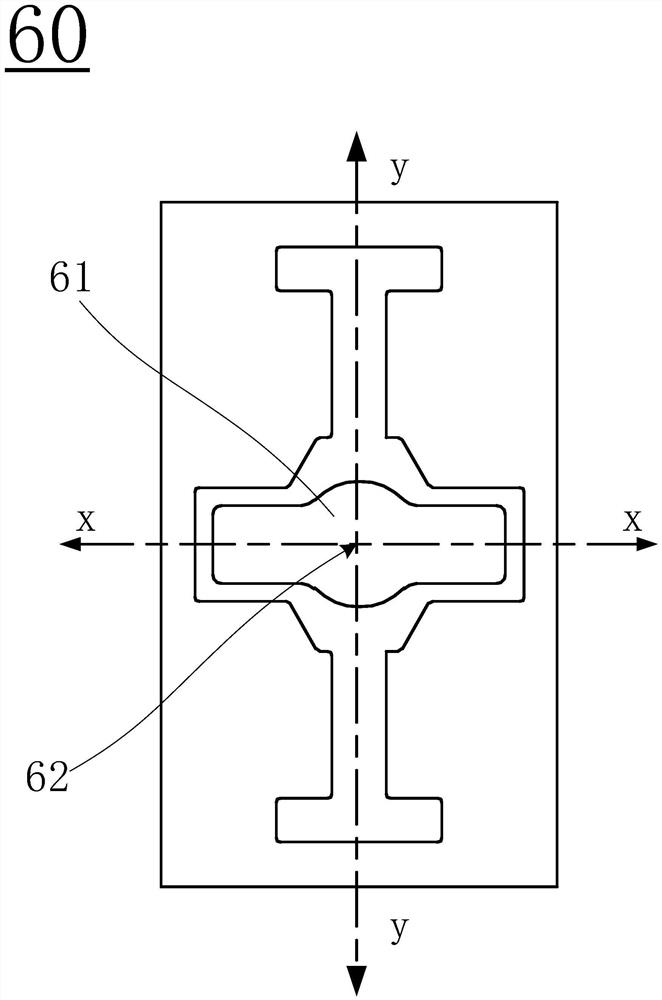
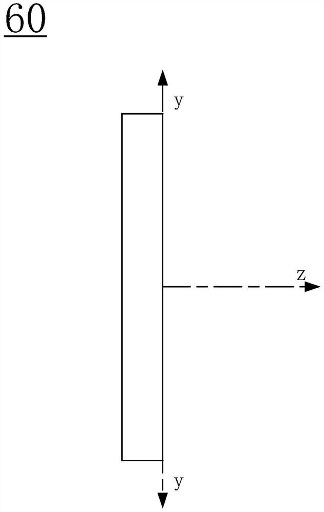
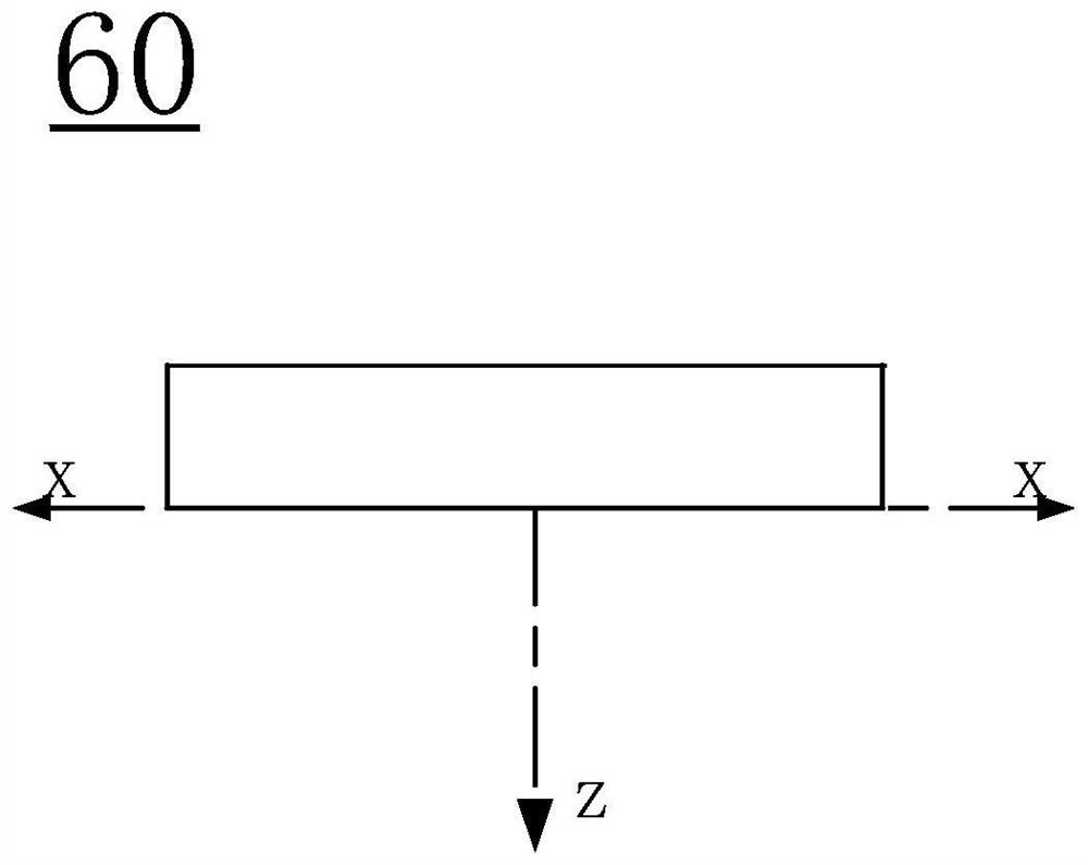
The invention relates to a galvanometer positioning tool and a laser printer. A galvanometer positioning tool comprises a base, a support and a rotating assembly, a bearing face is arranged on the base, and a first concave spherical face is arranged on the bearing face; the support is placed on the bearing face, a positioning assembly is arranged on the side face, facing the bearing face, of the support, a galvanometer is installed on the support, and the reflection center of the galvanometer is located on the sphere center of a sphere where the first concave spherical face is located. The rotating assembly comprises a first rotating rod and a second rotating rod, the first rotating rod is fixedly connected with the second rotating rod, the first rotating rod is rotationally connected with the base, the second rotating rod is slidably connected with the support, and the first rotating rod can drive the support to rotate with the y axis of the galvanometer as a rotating shaft when rotating relative to the base. The galvanometer can be adjusted to rotate around the y axis of the galvanometer by rotating the first rotating rod, the structure is simple, operation is convenient, and the precision and accuracy of the installation position of the galvanometer are effectively improved.

Description

technical field [0001] The invention relates to the technical field of laser printing, in particular to a galvanometer positioning tool and a laser printer. Background technique [0002] Laser printers have the advantages of fast printing speed and high imaging quality, and are widely used printing equipment at present. The laser scanning unit on the laser printer includes a laser, a scanning element and a photosensitive drum. The laser beam generated by the laser is reflected by the scanning element and then scanned on the photosensitive drum. The photosensitive drum cooperates with the toner cartridge to write information into the paper. [0003] Due to its small size, low price, easy adjustment, high frequency, and fast printing speed, the galvanometer is used as a scanning element on a laser printer, which greatly reduces the production cost of the laser printer and improves the performance of the laser printer. The galvanometer can not only reflect the laser beam, but ...

Claims


Application Information

Patent Timeline
IPC IPC(8): G03G15/04G03G15/043G02B26/10
CPCG03G15/04036G03G15/0435G02B26/105Y02P10/25B41J29/393G01B11/002
Inventor 邓自然黄宇传陈伯鹫王书方宋秀敏夏长锋何伟
Owner 佛山市顺德区蚬华多媒体制品有限公司
Learn More