High-speed emergent mode code error tester designed based on FPGA technology

A technology of burst mode and technical design, which is applied in the field of optical communication, can solve the problems of increasing output noise, achieve the effect of reasonable design mode, and guarantee precision and accuracy

Inactive Publication Date: 2015-12-09
CHENGDU LEWEISI TECH
View PDF2 Cites 0 Cited by
  • Summary
  • Abstract
  • Description
  • Claims
  • Application Information

AI Technical Summary

Problems solved by technology

The efficiency ratio of switching power supply is higher than tha

Method used


Image

  • High-speed emergent mode code error tester designed based on FPGA technology

Examples


Example Embodiment

[0049] Example 1:

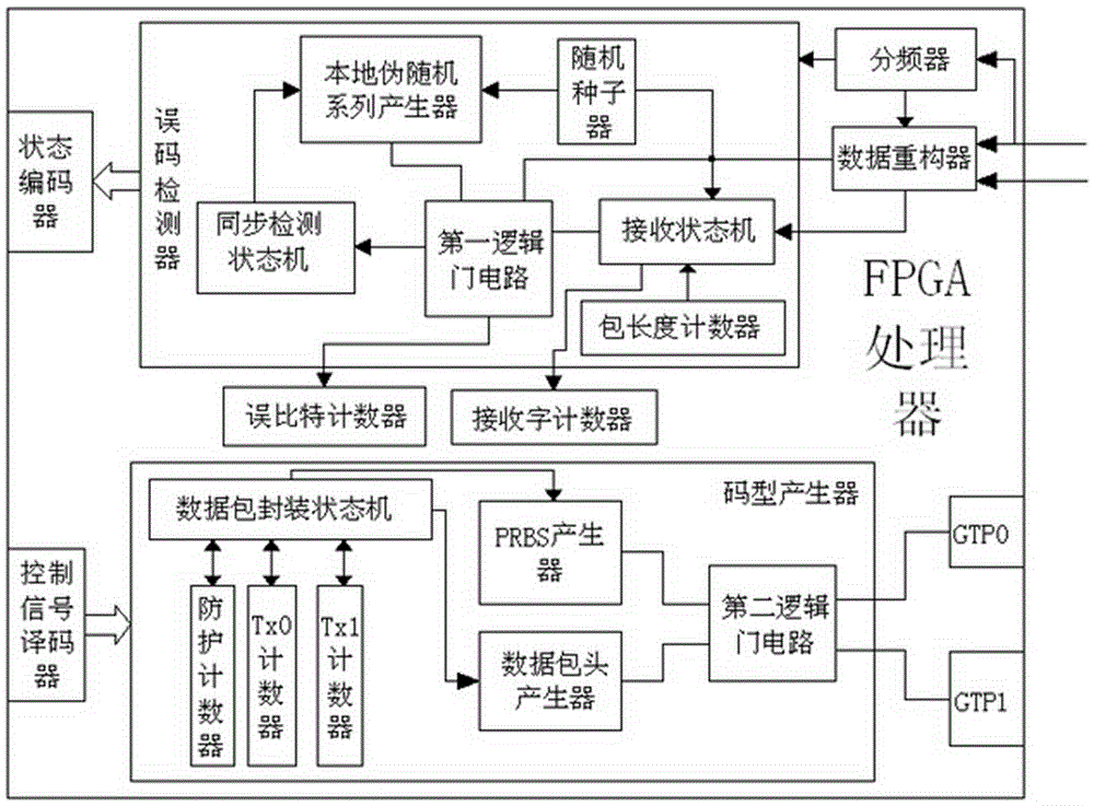
[0050] A high-speed burst mode bit error tester designed based on FPGA technology, a high-speed burst mode bit error tester designed with FPGA technology, can quickly and stably test and record bit errors, and its excellent processing performance, It can effectively ensure the precision and accuracy of error processing, such as figure 1 As shown, the following structure is specially provided: including an FPGA processor, a receiving end processing system and a transmitting end processing system are arranged on the FPGA processor, and the receiving end processing system includes a state encoder, a bit error detector and a counter system, the state encoder is connected to a bit error detector, and the bit error detector is connected to a counting system; the transmitter processing system includes a code pattern generator, a control signal decoder and a GTP solid core, the control signal decoder The encoder is connected to the code pattern generator, and the ...

Example Embodiment

[0051] Example 2:

[0052] This embodiment is further optimized on the basis of the above-mentioned embodiment, and further to better realize the present invention, such as figure 1 As shown, the following setting structure is specially adopted: a synchronous detection state machine, a local pseudo-random series generator, a random seeder, a first logic gate circuit, a receiving state machine and a packet length counter are arranged in the error detector, so The synchronization detection state machine is connected to a local pseudo-random series generator, the local pseudo-random series generator is connected to a random seeder, and the random seeder is connected to the receiving state machine; the first logic gate circuit is connected to the receiving state machine, and The receiving state machine is connected with the counting system, the first logic gate circuit is connected with the synchronization detection state machine, the first logic gate circuit is connected with the...

Example Embodiment

[0053] Example 3:

[0054] This embodiment is further optimized on the basis of the above-mentioned embodiment, and further to better realize the present invention, such as figure 1 As shown, the following setting structure is specially adopted: a frequency divider and a data reconstructor are also provided in the receiving end processing system, and the frequency divider is connected to the bit error detector; the data reconstructor is connected to the receiving state machine, so The data reconstructor is connected to the first logic gate circuit through a bus, and the random seeder is connected to the bus and connected to the receiving state machine through the bus.


PUM


Abstract

The invention discloses a high-speed emergent mode code error tester designed based on FPGA technology. The tester comprises an FPGA processer. A receiving end processing system and an emission end processing system are arranged on the FPGA processor. The receiving end processing system comprises a state coder, a code error detector and a counting system. The state coder is connected with the code error detector which is connected with the counting system. The emission end processing system comprises a code pattern generator, a control signal decoder and a GTP solid core. The control signal decoder is connected with the code pattern generator which is connected with the GTP solid core. A synchronous detection state machine, a local pseudorandom series generator, a random seed device, a first logic door circuit, a receiving state machine and a package length counting device are arranged in the code error detector. According to the invention, based on the FPGA technology, the tester can test and record error codes quickly and stably with excellent processing performance, and precision and accuracy of error code processing can be effectively ensured.

Description

technical field [0001] The invention relates to the technical field of optical communication, in particular, to a high-speed burst mode code error tester designed based on FPGA technology. Background technique [0002] FPGA (Field-ProgrammableGateArray), namely Field Programmable Gate Array, is the product of further development on the basis of PAL, GAL, CPLD and other programmable devices. It emerged as a semi-custom circuit in the field of application-specific integrated circuits (ASIC), which not only solved the shortcomings of the custom circuit, but also overcome the shortcomings of the limited number of gate circuits of the original programmable device. [0003] The circuit design completed in hardware description language (Verilog or VHDL) can be quickly programmed to the FPGA for testing after simple synthesis and layout, which is the mainstream technology of modern IC design verification. These editable elements can be used to implement some basic logic gate circui...

Claims


Application Information

Patent Timeline
IPC IPC(8): H04L12/26H04B10/079
CPCH04L43/0823H04B10/07953H04L43/50
Inventor 张宝怀
Owner CHENGDU LEWEISI TECH
Why Eureka
Try Eureka