

Differential signal connector
A differential signal and connector technology, which is applied in the direction of connection, two-part connection device, connection part protection grounding/shielding device, etc., can solve the problems of complex plug-in terminal and crimping terminal, large size of differential signal connector, etc., to achieve Solve the effect of large volume, realize miniaturization, and reduce volume
- Summary
- Abstract
- Description
- Claims
- Application Information
AI Technical Summary
Problems solved by technology
Method used
Image

Examples
Embodiment 1
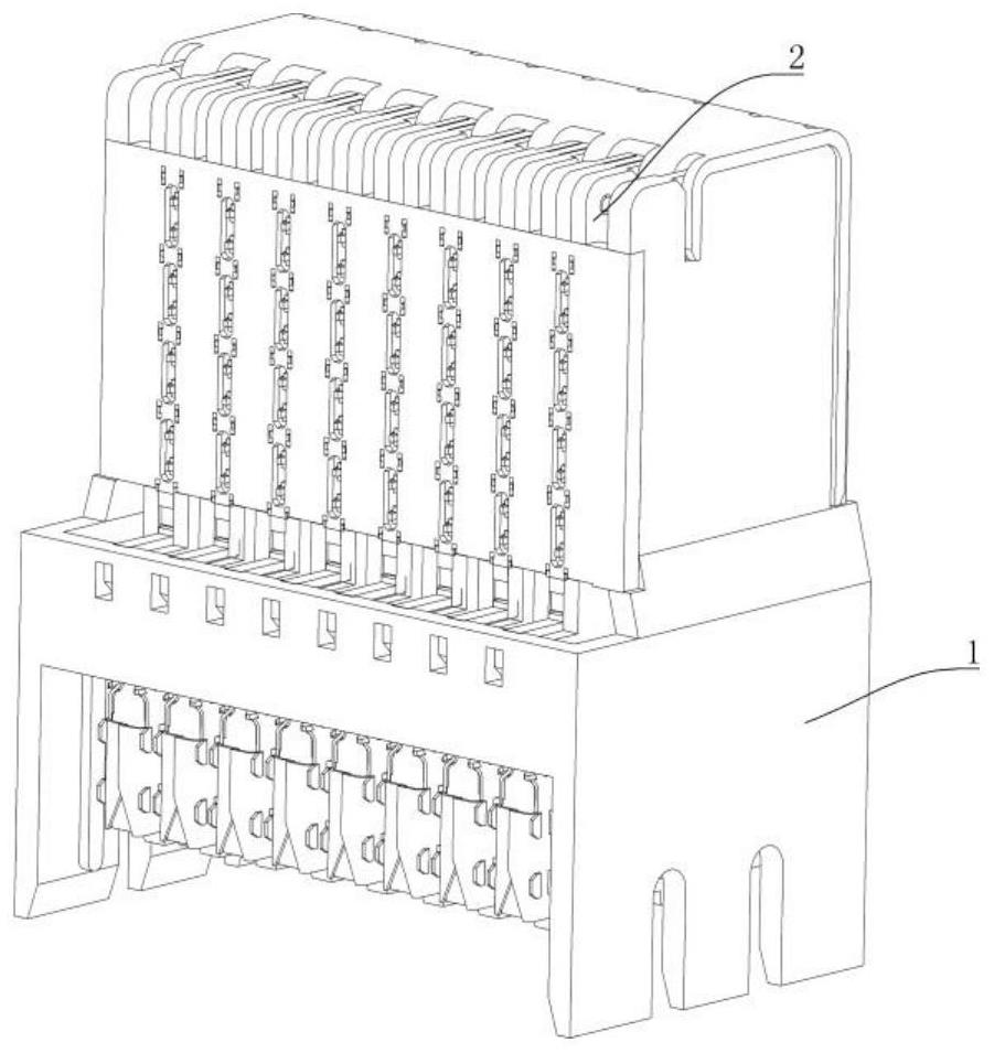
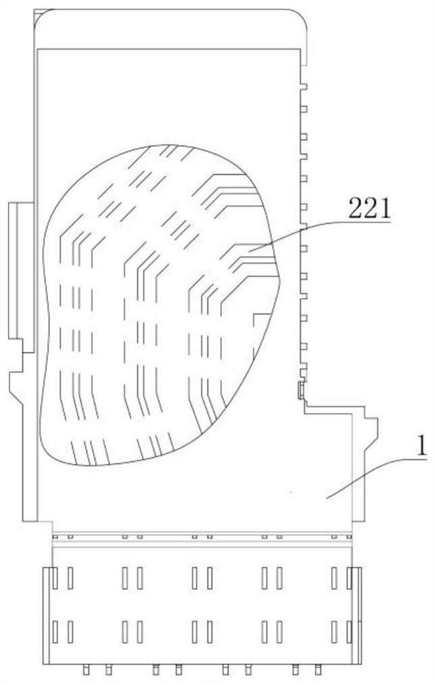
[0108] like Figure 1 to Figure 6 As shown, the differential signal connector of the present invention includes a housing 1 and differential signal modules 2 stacked and assembled on the housing 1. In this embodiment, there are eight differential signal modules 2 in total, but it is not limited thereto.
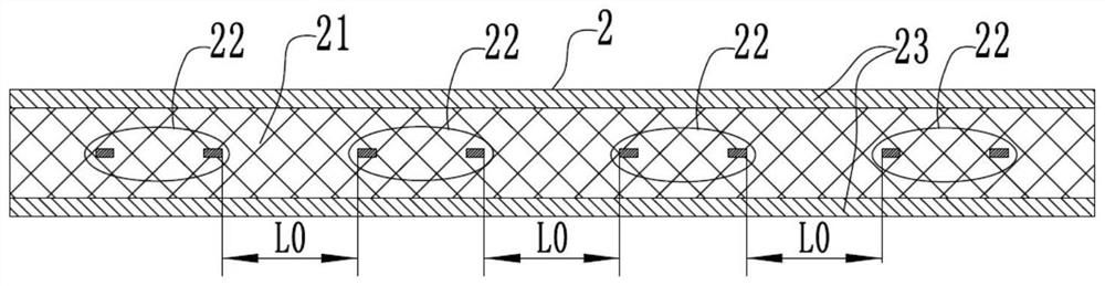
[0109] The differential signal module 2 includes a module insulator 21, a signal pair 22 and a shielding sheet 23. One differential signal module 2 includes four signal pairs 22, and each signal pair 22 includes two signal contacts 221. The line width is W, the material thickness is H, each signal contact piece 221 is embedded in the module insulator 21, and the signal contact piece 221 in this embodiment is a bent contact piece. In this embodiment, the distance between the two signal contacts 221 of each signal pair 22 is equal, and is always L2. The module insulator 21 is plate-shaped, and the differential signal modules 2 are arranged on the casing 1 in parallel. The arr...
Embodiment 2
[0117] The structure of the differential signal connector in this embodiment differs from that in Embodiment 1 only in that: Figure 8 and Figure 7 As shown, in the same differential signal module 2, the crimping end contacts of adjacent signal pairs 22 are lifted to different sides of the differential signal module, thereby making the signal contacts of adjacent signal pairs 22 crimp end contacts on the The conductive contact surface 2211 faces opposite to ensure the contact effect of the crimping terminal in the vibration environment.
Embodiment 3
[0119] The difference between the structure of the differential signal connector in this embodiment and the second embodiment is only that: Figure 10 and Figure 9 As shown, among the two adjacent differential signal modules 2, the signal pair 22 on one differential signal module and the adjacent signal pair 22 on the other differential signal module are arranged staggered in the arrangement direction of the two differential signal modules, and The offset distance L4 of the adjacent signal pairs of two adjacent differential signal modules in the arrangement direction of the differential signal modules is 1 mm-1.5 mm, and in this embodiment, the L4 is 1 mm. That is, in the arrangement direction of the differential signal modules 2, there is a 1 mm deviation between the center lines of the corresponding signal pairs 22 on the adjacent layer differential signal modules 2, thereby reducing the difference between adjacent signal pairs on the adjacent layer differential signal modu...
PUM
 Abstract
Description
Claims
Application Information