
Welding equipment for positioning piece of heating base

A technology of welding equipment and positioning parts, which is applied in the field of welding equipment for positioning parts of heating bases, can solve the problems of automatic bonding of heat-conducting substrates without heating elements, etc., achieve the effects of convenient automatic assembly, low welding efficiency, and reduced production costs

Pending Publication Date: 2022-05-27
FOSHAN IROBOT AUTOMATIC
View PDF0 Cites 0 Cited by
  • Summary
  • Abstract
  • Description
  • Claims
  • Application Information

AI Technical Summary

Problems solved by technology

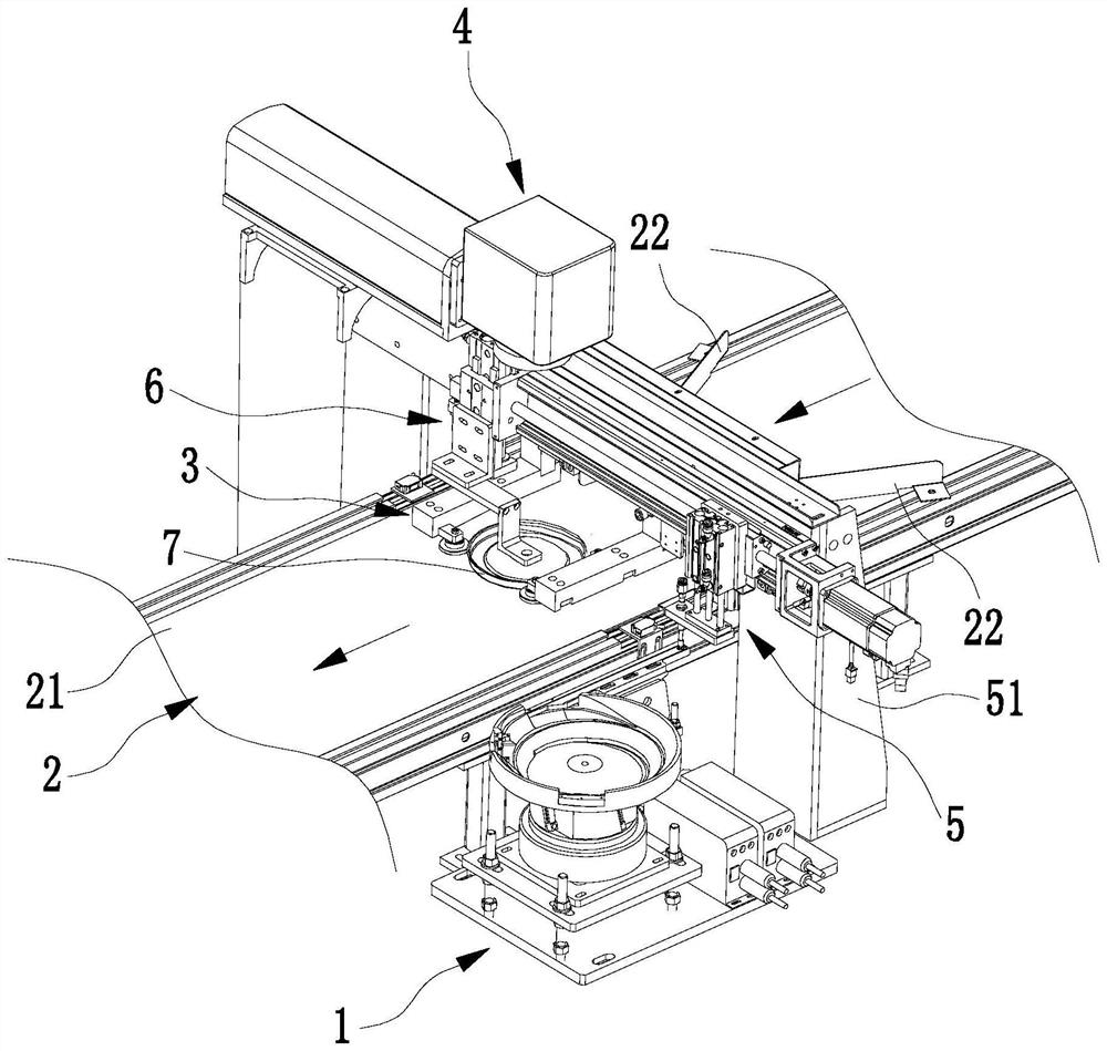
[0004] The purpose of the present invention is to solve the problem that there is no accurate reference for the heat-conducting base of the existing heating base for the automatic joining of the heating body, and to provide a welding equipment for the positioning part of the heating base. The adsorption device absorbs and transfers the positioning part to the preset position of the base where the positioning jig is positioned, and welds the positioning part through the laser welding device to achieve precise positioning of the heat-conducting substrate, and can accurately weld the positioning part on the predetermined position of the heat-conducting substrate

Method used


Image

  • Welding equipment for positioning piece of heating base
  • Welding equipment for positioning piece of heating base
  • Welding equipment for positioning piece of heating base

Examples


Embodiment Construction

[0034] The technical solutions of the present invention will be described below with reference to the accompanying drawings and specific embodiments.

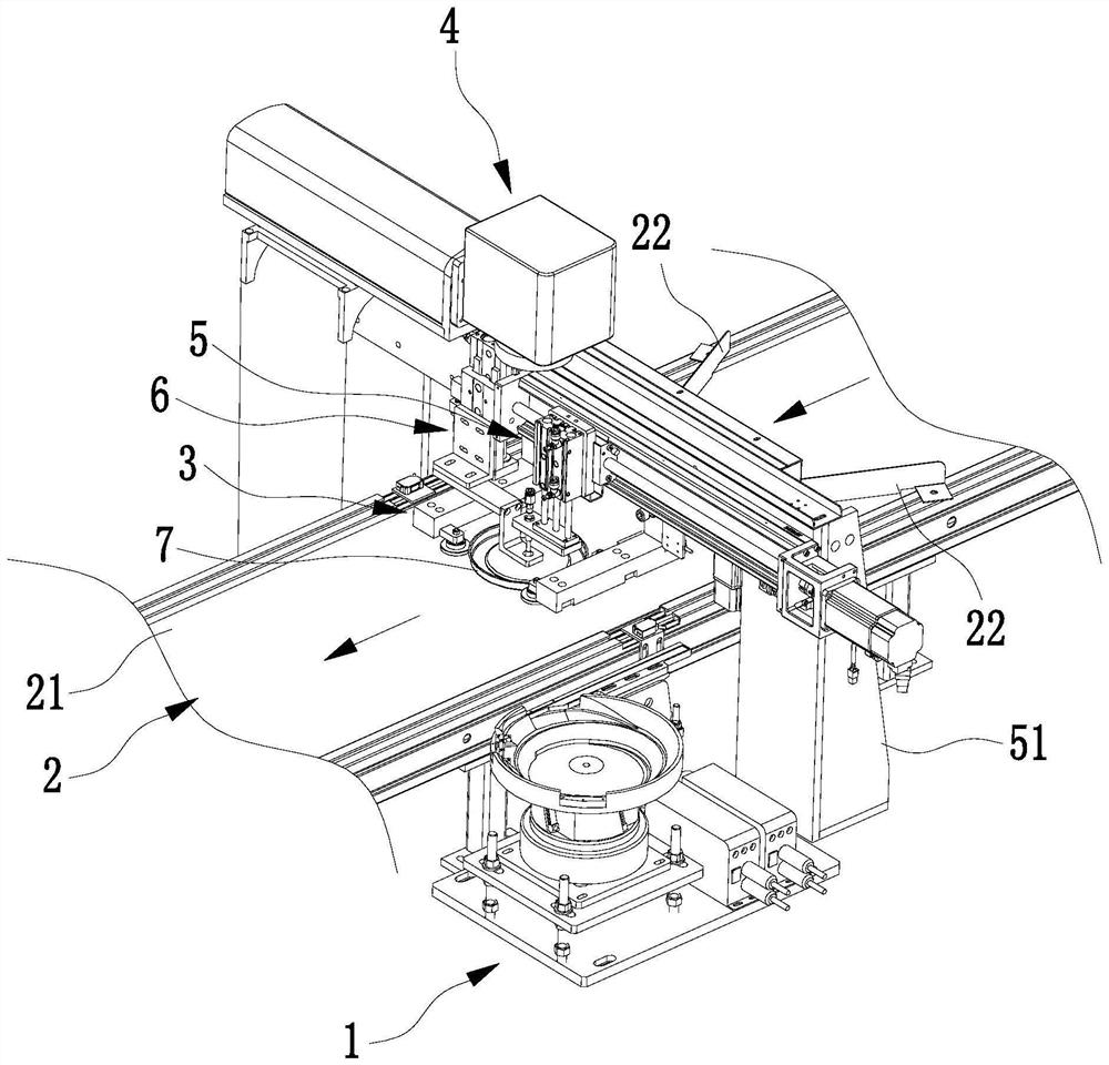
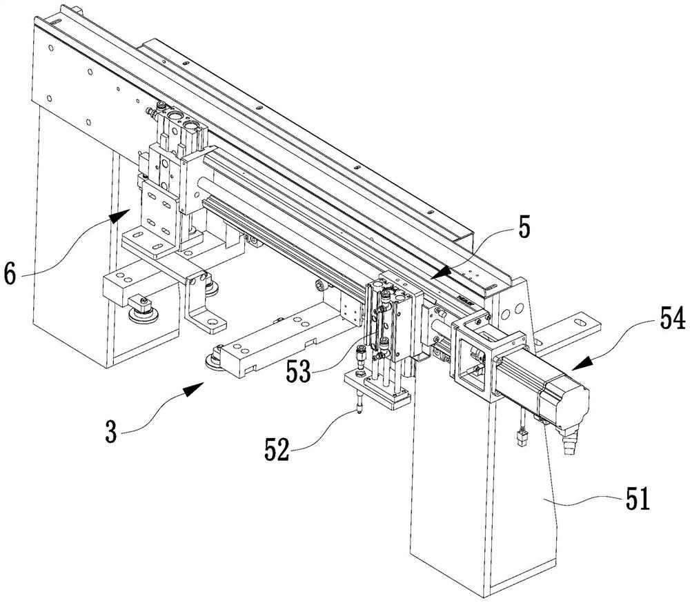
[0035] see figure 1 , figure 2 , image 3 and Figure 7 , the heating base positioning member welding equipment in this embodiment includes a conveying device 1, a feeding device 2, a centering device 3, a laser welding device 4, a transfer mechanism 5 and a welding guide mechanism 6, and the conveying device 1 includes a positioning member. 71 conveyors 12 and helical vibrating discs 11 are arranged and conveyed. The outlet of the helical vibrating discs 11 is connected to the feeding end of the conveyor 12. The end of the conveyor 12 is equipped with a reclaiming part 130; the feeding device 2 includes The conveying surface 21 for conveying the heat-conducting substrate 7; the centering device 3 is arranged on the upper side of the conveying surface 21 for centering and positioning the heat-conducting substrate 7; the las...


PUM


Abstract

The invention provides heating base positioning piece welding equipment which comprises a conveying device, a feeding device, a centering device, a laser welding device and a transferring mechanism, the conveying device comprises a conveyor used for arranging and conveying positioning pieces, and a material taking part is arranged at the tail end of the conveyor; the feeding device comprises a conveying face used for conveying the heat conduction base body. The centering device is arranged on the upper side of the conveying face and used for centering and positioning the heat conduction base body. The laser welding device is arranged above the centering device and used for welding the positioning piece placed on the upper side of the heat conduction base body centered by the centering device. The transfer mechanism comprises a vacuum adsorber for sucking the positioning piece, a first driving device for driving the vacuum adsorber to lift and a second driving device for driving the first driving device to enable the vacuum adsorber to move between the material taking part and the middle part of the centering device; according to the welding equipment for the positioning piece of the heating base, the positioning piece can be accurately welded to the middle of the metal heat conduction base body.

Description

technical field [0001] The invention relates to the technical field of heating base welding, in particular to welding equipment for heating base positioning parts. Background technique [0002] The heating base of the present invention mainly refers to a structure in which a heating body (such as an aluminum heating element) is welded on a metal heat-conducting substrate (such as a stainless steel kettle heating base). [0003] The existing heating bottom is generally semi-automatic welding, that is, the production personnel place the aluminum heating element on the metal heat-conducting base, and then weld the aluminum heating element to the metal heat-conducting base by welding equipment (such as brazing equipment). In order to ensure that the aluminum heating element is placed at a predetermined position, it is necessary to set a positioning piece on the metal heat-conducting base for positioning and centering the aluminum heating element as a reference, wherein the posit...

Claims


Application Information

Patent Timeline
Patent Type & Authority Applications(China)
IPC IPC(8): B23K26/21B23K26/70B65G47/14B65G47/91B65G47/24
CPCB23K26/21B23K26/70B65G47/1421B65G47/912B65G47/24Y02P70/50
Inventor 农百乐杨海广
Owner FOSHAN IROBOT AUTOMATIC
Learn More