Positioning device for office furniture production cutting

A positioning device and furniture technology, applied in the direction of grinding drive devices, manufacturing tools, metal processing equipment, etc., can solve the problems of low work efficiency, manual measurement, etc., and achieve the effect of improving work efficiency

Pending Publication Date: 2022-05-27
西安锐达圣电子科技有限公司
View PDF0 Cites 0 Cited by
  • Summary
  • Abstract
  • Description
  • Claims
  • Application Information

AI Technical Summary

Problems solved by technology

[0002] As we all know, the positioning device for office furniture production and cutting is an auxiliary device for furniture cutting and positioning, and it has been widely used in the field of furniture production; an existing positioning device for office furniture production and cutting includes a base plate, a grinding wheel Components, guide rails and clips, the grinding wheel assembly is installed on the top of the right part of the bottom plate, the two sets of guide rails are installed on the top left of the bottom plate, and the two sets of clips are slidingly connected with the two sets of guide rails; an existing positioning device for production and cutting of office furniture is used At the same time, the two ends of the plank are respectively clamped on two sets of clips, and the clips are pushed to make the grinding wheel assembly cut the plank; in the use of an existing positioning device for production and cutting of office furniture, it is found that manual measurement is required when the plank is cut. Marking is required for cutting, resulting in lower work efficiency

Method used


Image

  • Positioning device for office furniture production cutting
  • Positioning device for office furniture production cutting
  • Positioning device for office furniture production cutting

Examples


Embodiment Construction

[0018] The specific embodiments of the present invention will be described in further detail below with reference to the accompanying drawings and embodiments. The following examples are intended to illustrate the present invention, but not to limit the scope of the present invention.

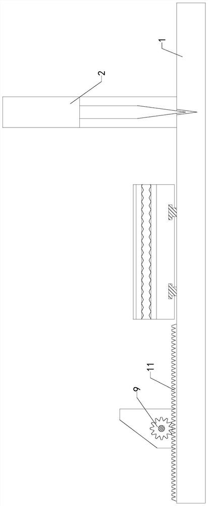
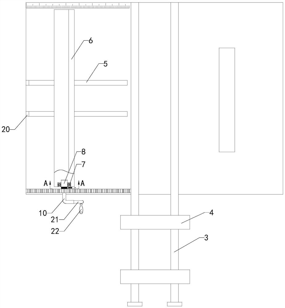
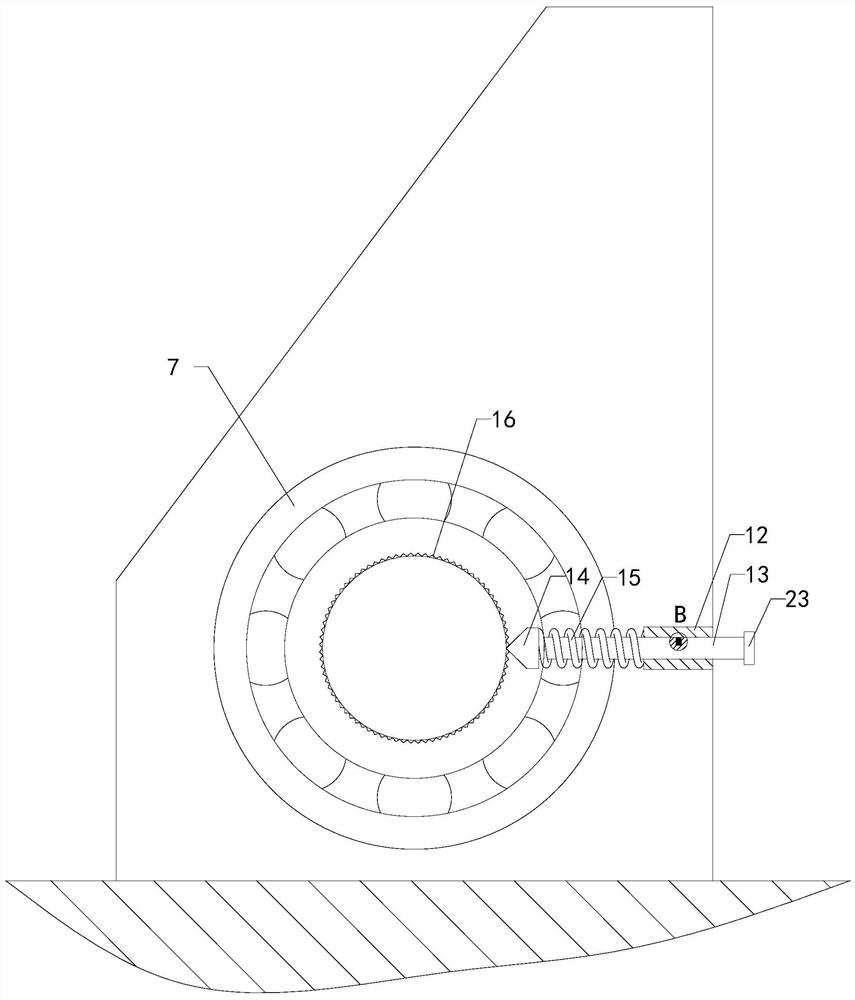
[0019] like Figure 1 to Figure 4 As shown, a positioning device for production and cutting of office furniture of the present invention includes a base plate 1, a grinding wheel assembly 2, a guide rail 3 and a clip 4, the grinding wheel assembly 2 is installed on the top of the right part of the base plate 1, and two sets of guide rails 3 are installed on the base plate 1. At the top of the left part, two sets of clips 4 are slidingly connected with two sets of guide rails 3; it also includes baffle plate 6, bearing 7, shaft 8, gear 9, bending handle 10, rack 11, connecting block 12, sliding rod 13, stop block 14. The first spring 15, the second spring 18 and the button 19, two sets of slidi...


PUM


Abstract

The invention relates to the technical field of furniture production, in particular to a positioning device for office furniture production cutting, which can continuously process wood boards with the same size, avoids measurement and marking before each time of processing, and improves the working efficiency. Comprising a bottom plate, a grinding wheel assembly, guide rails and clamps, the grinding wheel assembly is installed at the right top end of the bottom plate, the two guide rails are installed at the left top end of the bottom plate, and the two clamps are slidably connected with the two guide rails; two groups of sliding grooves are formed in the top end of the left part of the bottom plate, the bottom end of the baffle plate is in sliding connection with the two groups of sliding grooves, the front end of the baffle plate is rotatably connected with the shaft through the bearing, the front end of the shaft is connected with the rear end of the gear, and the front end of the gear is connected with the rear end of the bent handle; the bottom end of the rack is connected with the top end of the left front portion of the bottom plate, and the bottom end of the gear is meshed with the top end of the rack.

Description

technical field [0001] The invention relates to the technical field of furniture production, in particular to a positioning device for production and cutting of office furniture. Background technique [0002] As we all know, the positioning device for office furniture production and cutting is an auxiliary device for furniture cutting and positioning, which has been widely used in the field of furniture production; an existing positioning device for office furniture production and cutting includes a base plate, a grinding wheel Components, guide rails and clips, the grinding wheel component is installed on the top of the right part of the bottom plate, the two sets of guide rails are installed on the top of the left part of the bottom plate, and the two sets of clips are slidably connected with the two sets of guide rails; an existing positioning device for office furniture production and cutting is used When the two ends of the board are clamped on two sets of clips respect...

Claims


Application Information

Patent Timeline
Patent Type & Authority Applications(China)
IPC IPC(8): B24B27/06B24B41/06B24B47/22
CPCB24B27/06B24B27/0683B24B41/06B24B47/22
Inventor 彭悦王岁娜李菲菲
Owner 西安锐达圣电子科技有限公司
Why Eureka
Try Eureka