Printing equipment capable of rapidly drying printing ink

A fast drying and printing ink technology, applied in general parts of printing machinery, printing, printing machines, etc., can solve the problems of wasting energy, incomplete ink drying, etc., and achieve the effect of increasing evaporation, increasing temperature, and increasing drying rate

Pending Publication Date: 2022-05-27
深圳市思孚纸品包装有限公司
View PDF0 Cites 0 Cited by
  • Summary
  • Abstract
  • Description
  • Claims
  • Application Information

AI Technical Summary

Problems solved by technology

[0004] The purpose of the present invention is to provide a printing equipment for rapid drying of printing ink, which has the advantage of adjusting the drying intensity through the paper-feeding speed, and solves the problem of incomplete drying of ink or waste of energy

Method used


Image

  • Printing equipment capable of rapidly drying printing ink
  • Printing equipment capable of rapidly drying printing ink
  • Printing equipment capable of rapidly drying printing ink

Examples


Embodiment 1

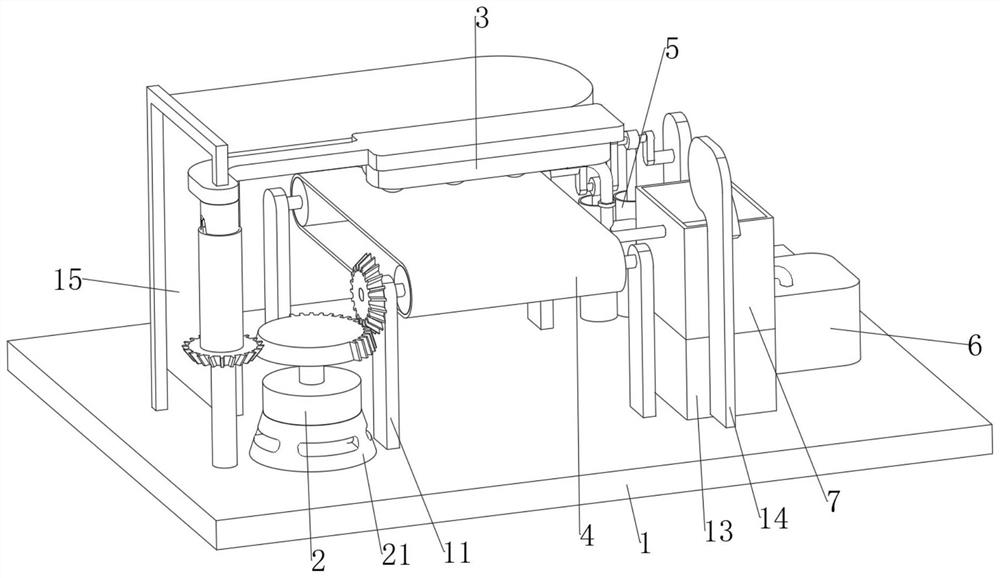
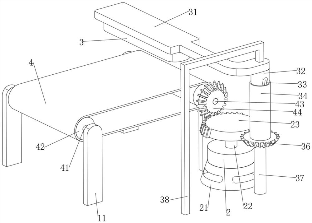
[0029] The present invention provides a technical solution: a printing ink rapid drying printing apparatus, comprising a load-bearing plate 1 and an ink printer 3, a load-bearing plate 1 fixed connection to four first support plates 11 and motor frame 21, each two first support plates 11 on the opposite surface of the fixed axis rotation connection with the first rotation axis 41 and the second rotation axis 43, the second rotation axis 43 extends out of the first support plate 11 at one end fixed connection has a first complete bevel gear 44, The first rotating shaft 41 and the second rotating shaft 43 are provided with a conveyor mechanism for transmitting the paper to be printed, the load-bearing plate 1 is connected to the rotating rod 37 on the fixed shaft rotation, the upper surface of the rotating rod 37 is fixed to be connected to the second complete bevel gear 36, the second complete bevel gear 36 is provided with a printing mechanism for printing paper, the motor frame 2...

Embodiment 2

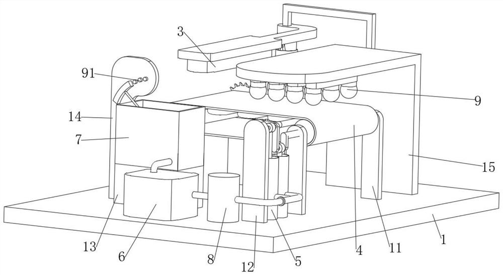
[0044] Substantially the same as Example I, further, the load-bearing plate 1 is provided with a heating mechanism for increasing the temperature of the printing environment, the heating mechanism comprises a heater 8 fixed to the load-bearing plate 1, the first delivery pipe 55 runs through the heater 8, the second conveyor pipe 57 is provided with a bending section, the bending section is located directly below the conveyor belt 4.

[0045] See Figure 5 and Figure 7 , when the water in the water tank 6 passes through the heater 8, the water will heat up into a higher temperature of water, and then flow into the second conveyor pipe 57 through the piston cylinder 57, because the second conveyor pipe 57 is provided with a bending section, the bending section is located directly below the conveyor belt 4, so that the temperature of the surrounding environment of the conveyor belt 4 is increased, thereby increasing the evaporation of the ink, thereby assisting in increasing the dryin...


PUM


Abstract

The printing equipment comprises a bearing plate and an ink printer, four first supporting plates and a motor frame are fixedly connected to the bearing plate, and a first rotating shaft and a second rotating shaft are rotationally connected to the opposite faces of every two first supporting plates through fixed shafts correspondingly; the end, extending out of the first supporting plate, of the second rotating shaft is fixedly connected with a first complete bevel gear, the first rotating shaft and the second rotating shaft are provided with a conveying mechanism used for conveying paper needing to be printed, a rotating rod is rotationally connected to the bearing plate through a fixed shaft, and the upper surface of the rotating rod is fixedly connected with a second complete bevel gear. A printing mechanism used for printing paper is arranged on the second complete bevel gear, a motor is fixedly connected to the motor frame, and the output end of the motor is fixedly connected with an output shaft. Through cooperation of the whole structure, the effects that the printing mechanism and the conveying mechanism cannot work at the same time, and the drying strength of printed paper can be adjusted through the paper feeding speed are achieved.

Description

Technical field [0001] The present invention relates to the technical field of printing equipment, specifically a printing apparatus for rapid drying of printing inks. Background [0002] Printing text and image machines, modern printing machines are generally composed of plate loading, inking, embossing, paper feeding (including folding) and other mechanisms. [0003] At present, most of the printing equipment in the printing after the completion of the drying, the printing of the finished paper drying, due to the irreconcilability of the drying equipment, so that the speed of the paper rate will cause the ink drying is not complete or waste energy, so we need a printing ink rapid drying printing equipment to solve the above problems. Contents of the Invention [0004] Object of the present invention is to provide a printing apparatus for rapid drying of printing inks, having the advantage of adjusting the drying strength by the paper pass rate, solving the problem of incomplet...

Claims


Application Information

Patent Timeline
Patent Type & Authority Applications(China)
IPC IPC(8): B41F23/04B41F1/28B65H29/16
CPCB41F23/0443B41F23/0453B41F23/0466B41F1/28B65H29/16B65H2701/1131B65H2701/176Y02P70/10
Inventor 黄冰钟美娟曾旭斌
Owner 深圳市思孚纸品包装有限公司
Why Eureka
Try Eureka