Dynamic measurement method, device and system for track settlement and deviation

A technology of dynamic measurement and settlement, applied to track, measuring instrument, track maintenance, etc., can solve the problem of large measurement error

Pending Publication Date: 2022-05-27
上海天链轨道交通检测技术有限公司
View PDF0 Cites 1 Cited by
  • Summary
  • Abstract
  • Description
  • Claims
  • Application Information

AI Technical Summary

Problems solved by technology

[0003] The purpose of the present invention is to provide a dynamic measurement method, device and system for track settlement and offset, so as to solve the measurement error of the pull-out guide height caused by the vibration during the running of the train in the existing non-contact pull-out guide height measurement bigger problem

Method used


Image

  • Dynamic measurement method, device and system for track settlement and deviation
  • Dynamic measurement method, device and system for track settlement and deviation
  • Dynamic measurement method, device and system for track settlement and deviation

Examples


Embodiment Construction

[0056] In order to make the objectives, technical solutions and advantages of the present invention clearer, the technical solutions of the present invention will be clearly and completely described below with reference to the specific embodiments of the present invention and the corresponding drawings. Obviously, the described embodiments are only some, but not all, embodiments of the present invention. Based on the embodiments of the present invention, all other embodiments obtained by those of ordinary skill in the art without creative efforts shall fall within the protection scope of the present invention. The technical solutions provided by the embodiments of the present invention will be described in detail below with reference to the accompanying drawings.

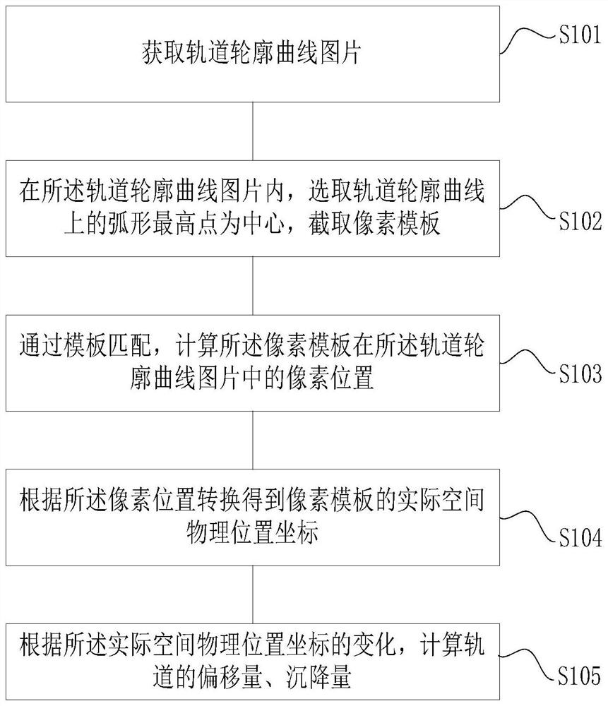
[0057] see figure 1 , an embodiment of the present invention provides a dynamic measurement method for track settlement and excursion, including:

[0058] S101, acquiring a picture of a track profile curve.

[00...


PUM


Abstract

The invention provides a dynamic measurement method, device and system for track settlement and deviation. The measuring method comprises the following steps: acquiring a track profile curve picture; in the track profile curve picture, selecting an arc-shaped highest point on a track profile curve as a center, and intercepting a pixel template; calculating the pixel position of the pixel template in the track profile curve picture through template matching; converting according to the pixel position to obtain the actual space physical position coordinate of the pixel template; and calculating the offset and settlement of the orbit according to the change of the actual space physical position coordinate. According to the system, the monitoring result is transmitted in real time, and the measurement of the pull-out lead height value of the contact line is compensated. And the measured data compensates the measured value of the non-contact pull-out lead height, so that the accurate space physical coordinate of the contact line is obtained.

Description

technical field [0001] The invention relates to the technical field of catenary detection, in particular to a dynamic measurement method, device and system for track settlement and deflection. Background technique [0002] In the electrified track, the transmission line erected along the rail is called the catenary, and its function is to directly transmit the electric energy obtained from the traction substation to the electric locomotive for use. The electric locomotive draws current through direct contact between the pantograph installed on the roof and the catenary wire. In order to ensure that the locomotive can obtain a continuous and stable current, the pantograph and the contact wire must be in reliable contact. Therefore, the quality and geometric parameters of the catenary will directly affect the transportation capacity of the electrified railway. With the increase of the train speed, the requirements for the contact suspension are getting higher and higher, so th...

Claims


Application Information

Patent Timeline
Patent Type & Authority Applications(China)
IPC IPC(8): E01B35/12
CPCE01B35/12
Inventor 陈旭东王奎解晨梁杰
Owner 上海天链轨道交通检测技术有限公司
Why Eureka
Try Eureka