
Concrete floor slab descending area slab surface shaping support construction method

A construction method and concrete technology, applied in the direction of formwork/formwork/work frame, connection parts of formwork/formwork/work frame, climate change adaptation, etc. The effect of quick installation and disassembly, cost saving and convenient construction

Pending Publication Date: 2022-05-27
CHINA MCC17 GRP
View PDF7 Cites 0 Cited by
  • Summary
  • Abstract
  • Description
  • Claims
  • Application Information

AI Technical Summary

Problems solved by technology

[0002] When designing reinforced concrete floor slab kitchens, bathrooms, balconies and other areas with falling slabs, the installation and reinforcement of the formwork on the slab surface will be very troublesome, and the construction is very cumbersome, time-consuming and labor-intensive
If the installation and reinforcement are not reliable, it will cause the cross-sectional size of the lower slab area of ​​the floor to fail to meet the requirements, leaking ribs, mold expansion and other quality hazards, resulting in unnecessary repairs and economic losses

Method used


Image

  • Concrete floor slab descending area slab surface shaping support construction method

Examples


Embodiment 1

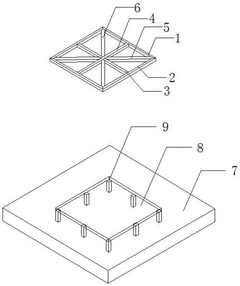
[0022] like figure 1 As shown in the figure, a construction method for shaping the slab surface in the descending area of ​​the concrete floor slab in this embodiment includes the following steps:

[0023] Step 1: First make the crossbar 1 (requires the horizontal net dimension length of the crossbar 1 and the lowering area 8), then make the vertical bar 2 (requires the horizontal bar 2 and the vertical length of the lowering area 8 are the same), and Arrange the outer side of the horizontal rod 1 and the outer side of the longitudinal rod 2 according to the cross-sectional size of the upper and lower plate area 8 of the floor slab 7, and cut off the overlapping parts of the two ends and then weld and fix them;

[0024] Step 2: Next, make the inner longitudinal rod 4 (the length of the inner longitudinal rod 4 is required to be the length of the longitudinal rod 2 minus twice the width of the transverse rod 2), and place the inner longitudinal rod 4 in the center of the transv...


PUM


Abstract

The invention discloses a concrete floor slab descending area slab surface shaping supporting construction method, and belongs to the technical field of building construction. The method comprises the following steps that firstly, transverse rods are manufactured, then longitudinal rods are manufactured, and the outer sides of the transverse rods and the outer sides of the manufactured longitudinal rods are placed according to the section size of a floor descending area of a floor; secondly, an inner longitudinal rod is manufactured, and the inner longitudinal rod is placed in the middle of the inner side of the transverse rod and is welded and fixed; thirdly, an inner transverse rod is manufactured, and the inner transverse rod and the inner longitudinal rod are placed in the middle of the inner side of the longitudinal rod; fourthly, an inclined supporting rod A and an inclined supporting rod B are manufactured, and the inclined supporting rod A and the inclined supporting rod B are placed in the diagonal direction of the transverse rod and the longitudinal rod; fifthly, cushion blocks are placed on the inner side of the plate descending area one by one; and sixthly, concrete is poured, formed, cured and then dismantled. The device can be quickly mounted and dismounted, is convenient to construct, can be repeatedly used, saves time and labor, and effectively saves the cost.

Description

technical field [0001] The invention relates to the technical field of building construction, and more particularly, to a construction method for slab surface shaped support in the descending area of ​​a concrete floor slab. Background technique [0002] When designing reinforced concrete floor kitchens, bathrooms, balconies and other areas with lowered slabs, it will be very troublesome to install and reinforce the formwork on the slab surface, and the construction is very cumbersome, time-consuming and labor-intensive. If the installation and reinforcement are not reliable, it will cause quality hidden dangers such as the section size of the lowering area of ​​the floor that does not meet the requirements, leaking reinforcement, and mold expansion, resulting in unnecessary repairs and economic losses. SUMMARY OF THE INVENTION [0003] 1. The problem to be solved [0004] In view of the existing problems and deficiencies in the prior art, the present invention provides a...

Claims


Application Information

Patent Timeline
Patent Type & Authority Applications(China)
IPC IPC(8): E04G11/48E04G17/00
CPCE04G11/48E04G17/00Y02A30/60
Inventor 邹仕山刘成成
Owner CHINA MCC17 GRP
Learn More