
Kiln sealing device

A sealing device and kiln technology, which is applied to the sealing of engines, furnaces, furnace types, etc., can solve problems such as unsafe kiln body, inability to completely isolate air, uneven temperature, etc., reduce operating costs and maintenance costs, and solve Increased heat consumption and improved sealing effect

Pending Publication Date: 2022-05-27
睢县亚新智能科技环保有限公司
View PDF0 Cites 0 Cited by
  • Summary
  • Abstract
  • Description
  • Claims
  • Application Information

AI Technical Summary

Problems solved by technology

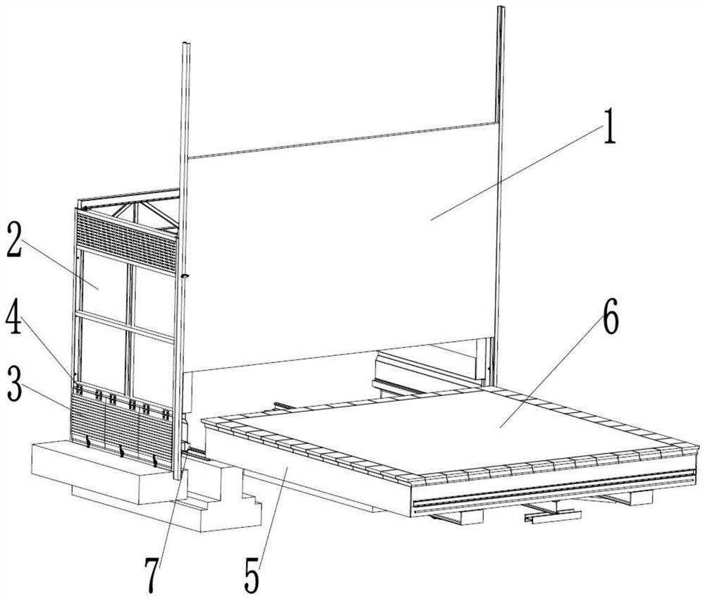
The use of ordinary tunnel kiln sand sealing groove and kiln car sand sealing skirt plate for sealing has the following disadvantages: (1) The ordinary tunnel kiln sand sealing groove needs to be filled with sand to seal, and the kiln car sand sealing skirt plate extends into the sand, and the kiln car travels During the process, the sand sealing skirt plate drives the sand to flow, and the sand filling degree in the sand sealing tank is not enough to completely isolate the air, so that the wrong air enters the kiln; (2) The sand sealing skirt plate of the kiln car will be deformed and different after running for a long time. Excessive thermal expansion will cause the kiln car to wear out, resulting in poor sealing, air leakage, and further cause the bottom temperature of the car to be too high to burn out the kiln car bearing, resulting in abnormal thermal system in the kiln, uneven temperature, and failure to reach the brick firing temperature. The quality of the fired products is poor, and even the situation of being unable to fire occurs; (3) In the production, it is common for the kiln car to scrape the kiln wall of the tunnel kiln (the kiln wall below the height of the main vehicle surface) and the sand-sealed groove, resulting in kiln The car was stuck in the kiln and could not move forward or backward. The staff had to "fire" to pull out the car until the fire had to be turned off and the kiln had to be shut down. Unsafe resources and kiln bodies increase operating and maintenance costs

Method used


Image

  • Kiln sealing device
  • Kiln sealing device
  • Kiln sealing device

Examples


Embodiment Construction

[0027] The technical solutions in the embodiments of the present invention will be clearly and completely described below with reference to the accompanying drawings in the embodiments of the present invention. Obviously, the described embodiments are only a part of the embodiments of the present invention, rather than all the embodiments. Based on the embodiments of the present invention, all other embodiments obtained by persons of ordinary skill in the art without creative efforts shall fall within the protection scope of the present invention.

[0028] The purpose of the present invention is to provide a kiln sealing device, so as to solve the above-mentioned problems in the prior art and improve the sealing effect of the kiln.

[0029] In order to make the above objects, features and advantages of the present invention more clearly understood, the present invention will be described in further detail below with reference to the accompanying drawings and specific embodiment...


PUM


Abstract

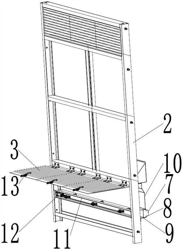
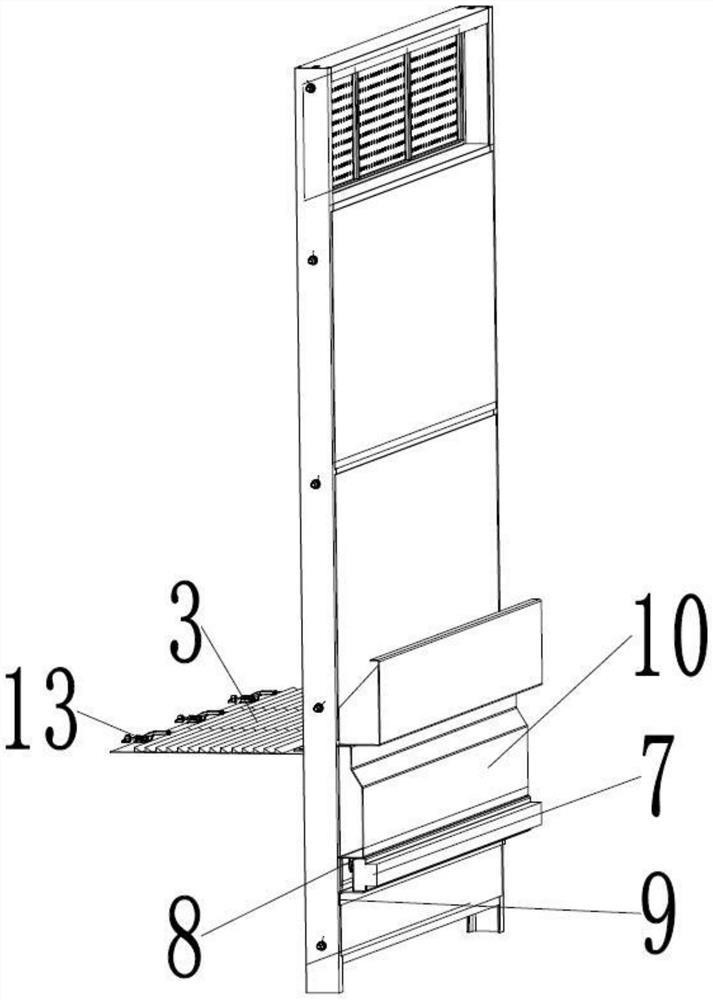
The invention discloses a kiln sealing device which comprises a plurality of sealing mechanisms, each sealing mechanism comprises a fixed part, a movable part and a sealing plate, each fixed part is fixedly arranged on a kiln wall, each movable part is connected with the corresponding fixed part through at least two telescopic structures, each telescopic structure comprises a first pipe fitting, a second pipe fitting and a spring, one end of each first pipe fitting is fixedly connected with the corresponding movable part, and the other end of each first pipe fitting is fixedly connected with the corresponding movable part. One end of the second pipe fitting is fixedly connected with the fixed part, the first pipe fitting and the second pipe fitting are sleeved with the spring, one end of the spring abuts against the movable part, and the other end of the spring abuts against the fixed part; one end of the sealing plate is fixedly connected with one side of the moving part away from the fixed part; a sliding groove is further formed in the kiln wall, the moving piece is in sliding fit with the sliding groove, and the other end of the sealing plate can stretch out of the sliding groove. A driving device and a transmission unit are arranged on the fixed part, and the driving device can drive the moving part to approach the fixed part through the transmission unit. According to the kiln sealing device, the sealing effect of the kiln is improved.

Description

technical field [0001] The invention relates to the technical field of kiln equipment, in particular to a kiln sealing device. Background technique [0002] In the prior art, the common tunnel kiln sand sealing groove and the kiln car sand sealing skirt are usually used to seal the kiln. The use of ordinary tunnel kiln sand sealing groove and kiln car sand sealing skirt for sealing has the following disadvantages: (1) The ordinary tunnel kiln sand sealing groove needs to be filled with sand to seal, the kiln car sand sealing skirt extends into the sand, and the kiln car travels During the process, the sand sealing skirt drives the flow of sand, and the filling degree of the sand in the sand sealing groove is not enough to completely isolate the air, so that the wrong air enters the kiln; (2) The sand sealing skirt of the kiln car will be deformed and different after running for a long time. Excessive thermal expansion causes the kiln car to wear out, resulting in poor seali...

Claims


Application Information

Patent Timeline
IPC IPC(8): F16J15/06F16J15/10F27B9/30
CPCF16J15/06F16J15/061F16J15/102F27B9/30Y02P40/60
Inventor 刘勤锋刘恩光许雷朋李帅江雁刘康宁
Owner 睢县亚新智能科技环保有限公司
Learn More