Laser sensor position adjusting device

A laser sensor and adjustment device technology, applied in the direction of supporting machines, machines/brackets, mechanical equipment, etc., can solve the problems of greater influence of the angle of light, wafer detection reliability and poor versatility, etc., to achieve good practical value , Improve reliability and versatility

Pending Publication Date: 2022-05-27
ADVANCED MATERIALS TECH & ENG INC
View PDF0 Cites 0 Cited by
  • Summary
  • Abstract
  • Description
  • Claims
  • Application Information

AI Technical Summary

Problems solved by technology

[0005] However, the position of the laser sensor on the bracket is fixed and has no adjustment function. Affected by the fixed angle of the laser sensor, it has a great influence on the angle of the light emitted by the laser sensor, resulting in poor reliability and versatility of wafer detection.

Method used


Image

  • Laser sensor position adjusting device
  • Laser sensor position adjusting device
  • Laser sensor position adjusting device

Examples


Embodiment Construction

[0034] The technical solutions in the embodiments of the present application will be clearly and completely described below with reference to the drawings in the embodiments of the present application. Obviously, the described embodiments are only a part of the embodiments of the present application, rather than all the embodiments. Based on the embodiments in the present application, all other embodiments obtained by those of ordinary skill in the art without creative work fall within the protection scope of the present application.

[0035] It should be noted that all the directional indications in the embodiments of the present application are only used to explain the relative positional relationship, motion situation, etc. between the components under a certain posture. If the specific posture changes, the directional indication Change accordingly.

[0036] The following disclosure provides many different embodiments or examples for implementing different structures of the...


PUM

PropertyMeasurementUnit
Central angleaaaaaaaaaa

Abstract

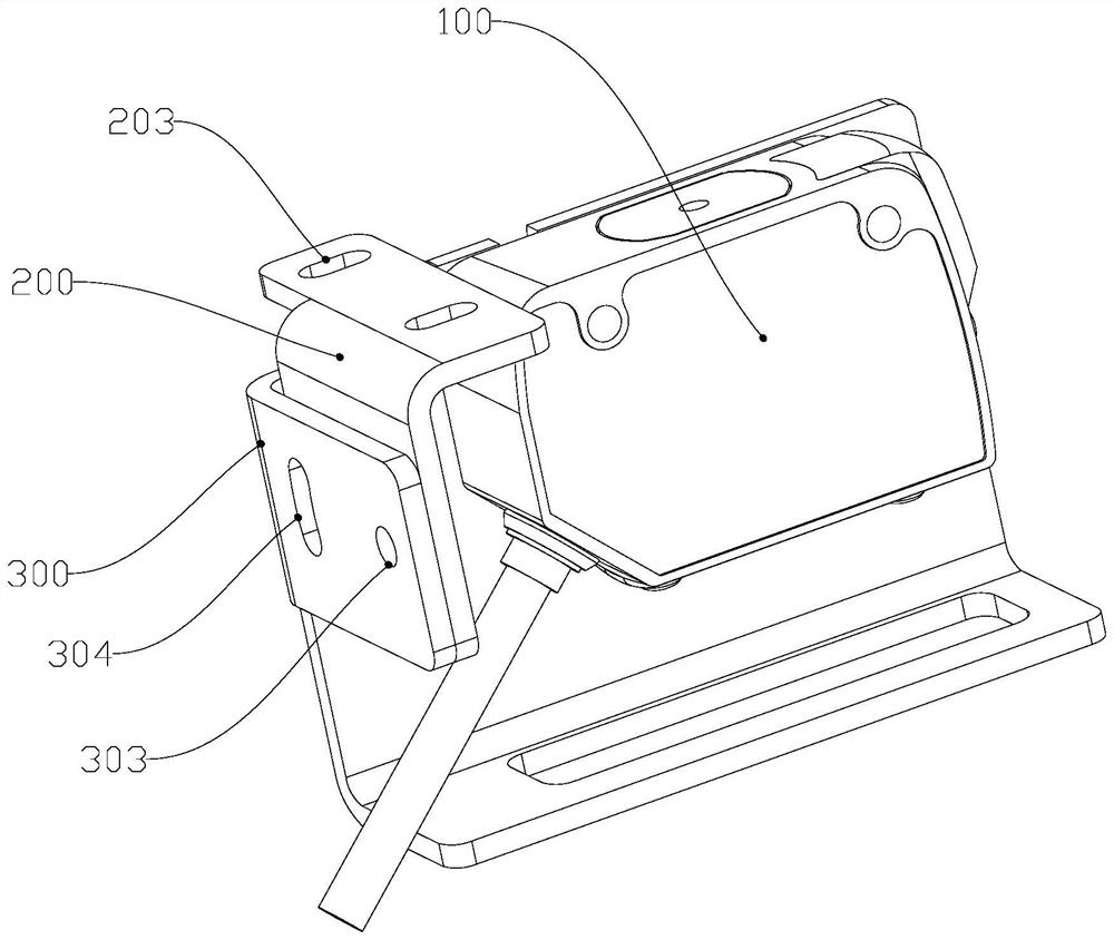
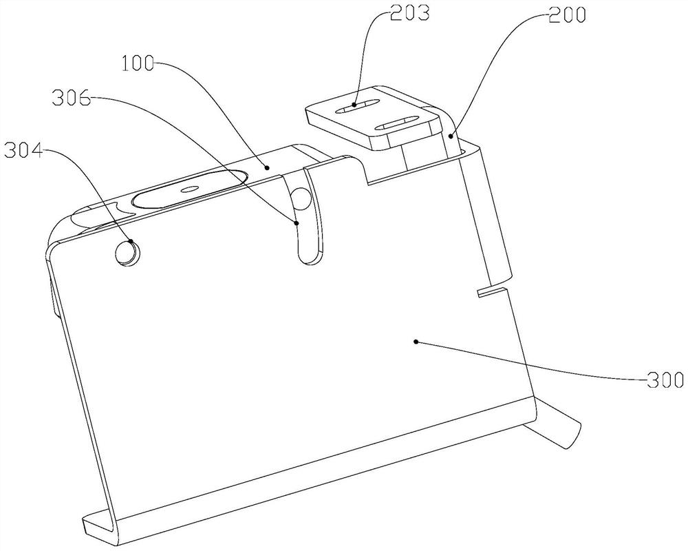
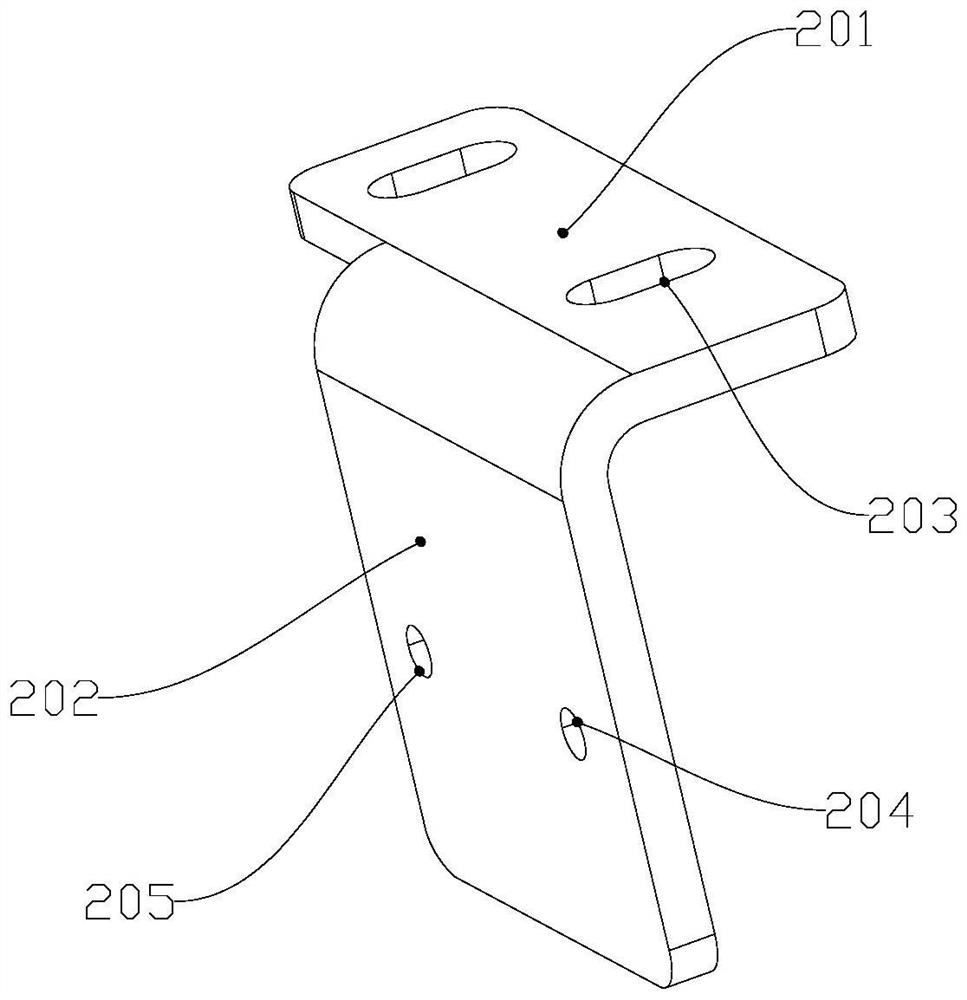
The invention belongs to the technical field of semiconductor processing, and particularly relates to a laser sensor position adjusting device. A first connecting piece of the position adjusting device comprises a first connecting plate and a second connecting plate which are fixedly connected, the first connecting plate is arranged in the first direction and can be movably connected to a carrier in the first direction, the second connecting plate is arranged in the second direction, and the second direction is perpendicular to the first direction; the second connecting piece is fixedly connected with a third connecting plate and a fourth connecting plate, the third connecting plate can swing around a first rotating shaft and is connected to the second connecting plate in a locked mode, the first rotating shaft is arranged in the first direction, the fourth connecting plate is arranged in the third direction, and the third direction is perpendicular to the first direction and the second direction. The laser sensor can swing around a second rotating shaft and is connected to the fourth connecting plate in a locked mode, and the second rotating shaft is arranged in the second direction. The mounting position of the laser sensor on the carrier can be adjusted, so that the use angle of the laser sensor is adjustable, the reliability and the universality of wafer detection are improved, and the practical value is very good.

Description

technical field [0001] The application belongs to the technical field of semiconductor processing, and in particular relates to a laser sensor position adjustment device. Background technique [0002] In the semiconductor industry, the transfer and transfer of wafers in the process chamber are realized by the lifting mechanism and the ejector mechanism. The limit of the ejector mechanism can greatly improve the positioning accuracy of wafer placement and wafer retrieval. [0003] During the wafer transport process, due to control and other reasons, a transfer error may occur, so that it cannot be guaranteed that the wafer can be correctly transferred to the wafer stage inside the reaction chamber, which will seriously affect the subsequent process. And if the wafer transfer is unsuccessful, the wafer is actually still on the manipulator. When the wafer is automatically retrieved after the process is over, an accident that the wafer collides with the thimble will occur, affec...

Claims


Application Information

Patent Timeline
IPC IPC(8): F16M11/04F16M11/06F16M11/16
CPCF16M11/04F16M11/043F16M11/06F16M11/16
Inventor 牛贞发孙文彬李庆伟
Owner ADVANCED MATERIALS TECH & ENG INC
Why Eureka
Try Eureka