Anticorrosion test method and anticorrosion test equipment for coated metallic material
- Summary
- Abstract
- Description
- Claims
- Application Information
AI Technical Summary
Benefits of technology
Problems solved by technology
Method used
Image
Examples
first embodiment
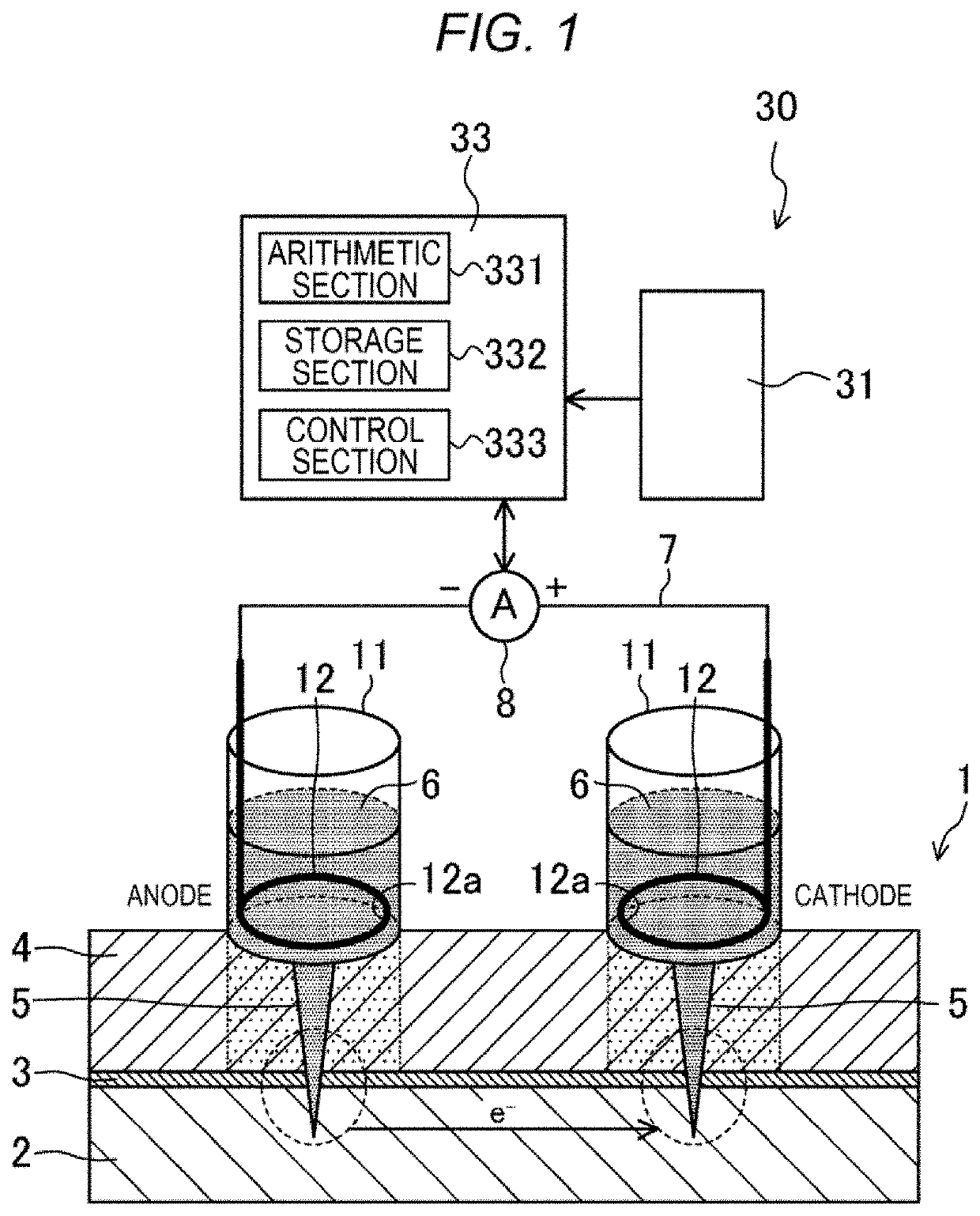
[0059]FIG. 1 illustrates an example of a principle of an anticorrosion test method and anticorrosion test equipment according to this embodiment. FIG. 1 illustrates a coated metallic material 1 and anticorrosion test equipment 30.
[0060]In the coated metallic material 1 in this embodiment, a metallic base material is formed with a chemical film 3 on a surface of a steel sheet 2 and is provided with an electrodeposition coating film 4 (a resin coating film) as a surface-treated film.
[0061]In the coated metallic material 1, an artificial flaw 5 that penetrates the electrodeposition coating film 4 and the chemical film 3 and reaches the steel sheet 2 is added at two mutually-separated positions.
[0062]
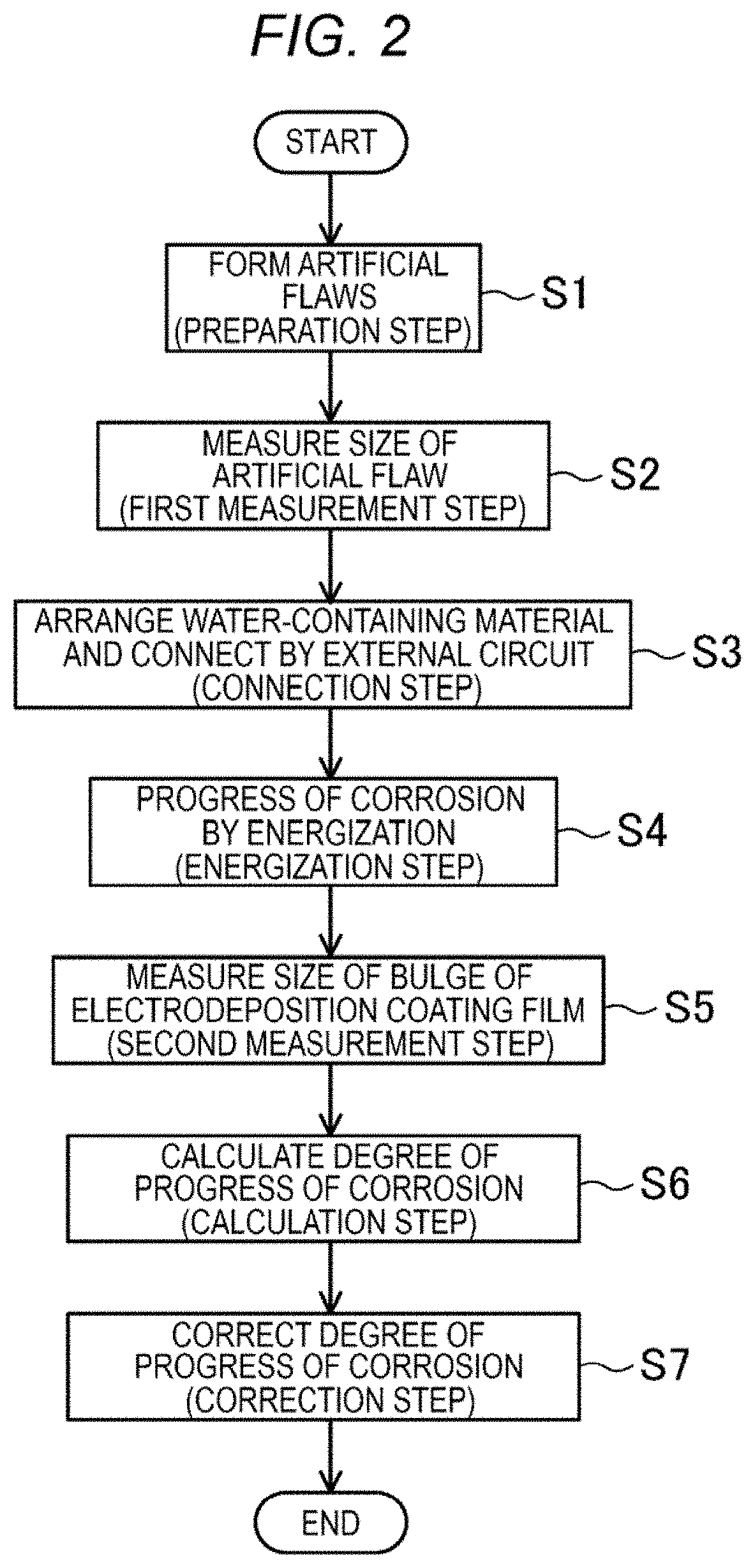
[0063]As illustrated in FIG. 1, anticorrosion test equipment 30 according to this embodiment includes a cylinder 11, an external circuit 7, energization means 8, a camera 31 (first measurement means, second measurement means, detection means), and a controller 33 (the first measurement mean...
experiment example
[0146]-Anticorrosion Test-
[0147]As illustrated in Table 1, as test materials (the coated metallic materials), three types of the test materials with the different coating materials for the electrodeposition coating film 4 and different electrodeposition baking conditions were prepared.
TABLE 1Test material123Electrodeposition140° C. ×160° C. ×140° C. ×baking condition15 minutes10 minutes20 minutesDiameter of10.20.2artificial flaw——0.42(mm)—0.60.6——1—1.51.5Temperature (° C.)50 65 65Holding time (minute)030 30Energization time (hour)50.50.5
[0148]In each of the test materials 1 to 3, the metallic base material is the steel sheet 2, the chemical film is zinc phosphate, a chemical conversion coating time is 120 seconds, and a thickness of the electrodeposition coating film 4 is 10 μm. The anticorrosion test was conducted for each of the test materials in the manner illustrated in FIG. 1.
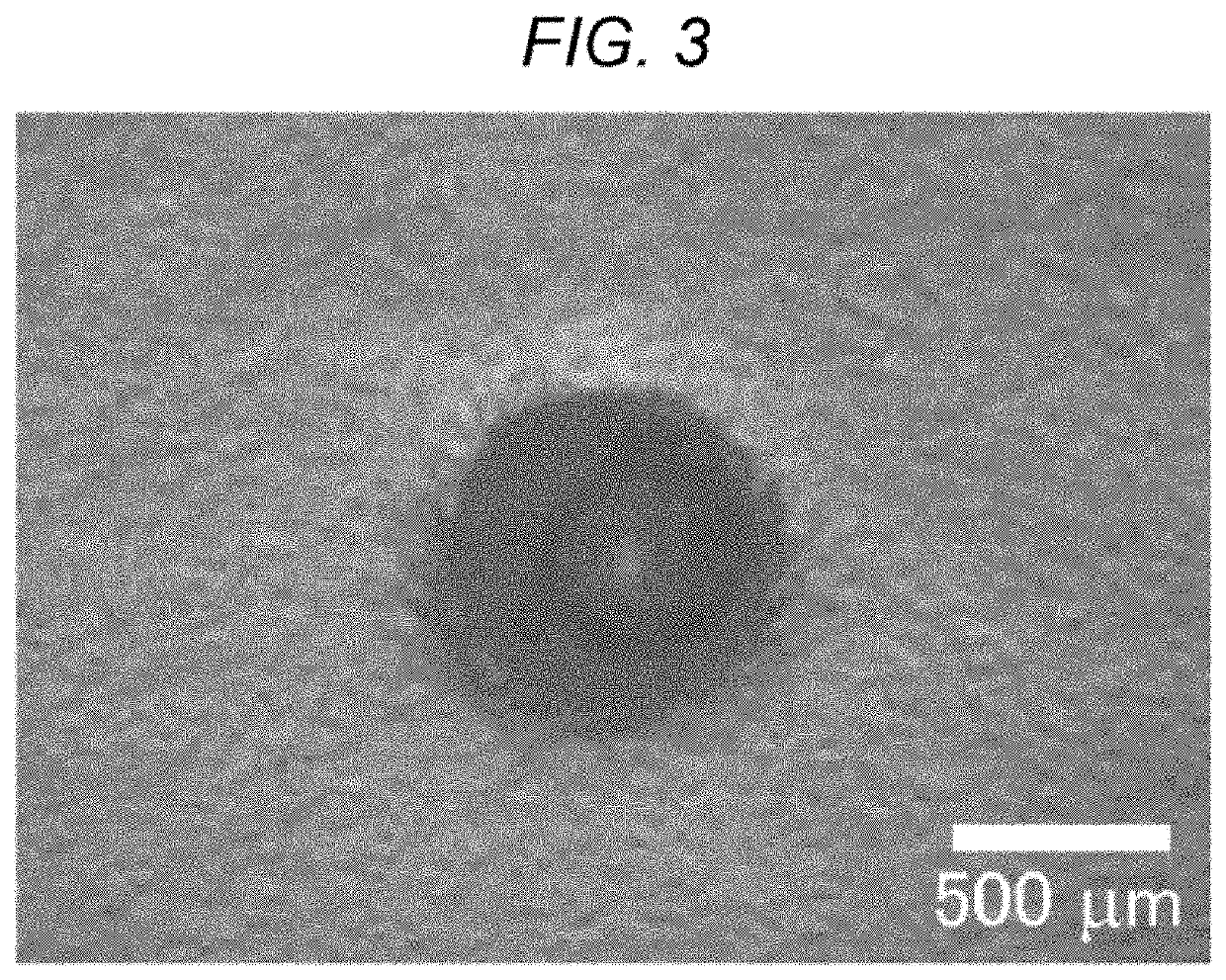
[0149]In each of the test materials 1 to 3, the Vickers hardness tester was used to form the artifici...
second embodiment
[0155]A detailed description will hereinafter be made on other embodiments according to the present disclosure. In the description of these embodiments, the same portions as those in the first embodiment will be denoted by the same reference signs and numerals, and the detailed description thereon will not be made.
[0156]In the first embodiment, the energization in the energization step S4 is of a constant current control type. However, the energization in the energization step S4 may be of a constant voltage control type.
[0157]More specifically, in FIG. 7, the current for the energization by the constant current control at 1 mA in the first embodiment is plotted (the test of the test material 1), and in FIG. 8, the current at the time when a constant voltage is applied is plotted, and the constant voltage is in such a magnitude that the current at 1 mA flows. In this anticorrosion test with the constant current control and this anticorrosion test with the constant voltage control, t...
PUM
 Abstract
Description
Claims
Application Information
 - R&D
- Intellectual Property
- Life Sciences
- Materials
- Tech Scout
- Unparalleled Data Quality
- Higher Quality Content
- 60% Fewer Hallucinations
Browse by: Latest US Patents, China's latest patents, Technical Efficacy Thesaurus, Application Domain, Technology Topic, Popular Technical Reports.
© 2025 PatSnap. All rights reserved.Legal|Privacy policy|Modern Slavery Act Transparency Statement|Sitemap|About US| Contact US: help@patsnap.com


