
Cleaning machine

A cleaning machine and casing technology, which is applied in the field of cleaning machines, can solve the problems of hindering the lifting of compression parts, hindering the flow of the cyclone of the cleaning machine, and not being able to smoothly realize the cyclone flow, so as to achieve the effect of improving performance

Active Publication Date: 2022-05-27
LG ELECTRONICS INC
View PDF8 Cites 0 Cited by
  • Summary
  • Abstract
  • Description
  • Claims
  • Application Information

AI Technical Summary

Problems solved by technology

If the compression part cannot return to its original position, the flow of the cyclone of the sweeper will be hindered, and the performance of the sweeper will be reduced.
[0012] Of course, if the upper part of the compression part is periodically cleaned, the dust can be removed, and the upper part of the compression part is not directly exposed when the dust cylinder is opened but is located inside. Therefore, if the compression part is not completely disassembled, Difficult to clean and therefore very inconvenient
[0013] In addition, the space between the compression part and the inner surface of the dust tube can be reduced to prevent the sucked air from flowing to the gap between the compression part and the inner surface of the dust tube, but in this way, the friction between the compression part and the dust tube , the lifting action of the compression part is hindered, and a large force is required to lift the compression part
Not only that, when the space between the compressing part and the inner surface of the dust cylinder is reduced, the air flow path of the sucked air will be blocked, and thus there may be a problem that the flow of the cyclone cannot be smoothly realized.
[0014] In addition, the conventional compression member is connected to the operation lever protruding to the outside of the cleaning machine so that the compression member can be operated from the outside, but a large load is concentrated on the connecting part connecting the operation rod and the compression member and its surroundings. Therefore, there is a problem that the compression parts are easily deformed or damaged
When the periphery of the connection part of the compression part is deformed, it interferes with the internal parts of the cleaning machine, which still leads to the problem of hindering the smooth lifting of the compression part.

Method used


Image

  • Cleaning machine
  • Cleaning machine
  • Cleaning machine

Examples


Embodiment Construction

[0065] Hereinafter, some embodiments of the present invention will be described in more detail with reference to the exemplary drawings. When adding symbols to the constituent elements in the respective drawings, the same constituent elements are used as much as possible even if they are shown in different drawings. In addition, in the description of the embodiment of the present invention, if it is judged that the specific description of the related well-known structure or function affects the understanding of the embodiment of the present invention, the detailed description is omitted.

[0066] In addition, when describing the components of the embodiment of the present invention, terms such as first, second, A, B, (a), and (b) will be used. Such terms are only used to distinguish the constituent elements from other constituent elements, and the terms do not limit the nature, order, or sequence, etc. of the constituent elements. When it is described that a certain constitue...


PUM


Abstract

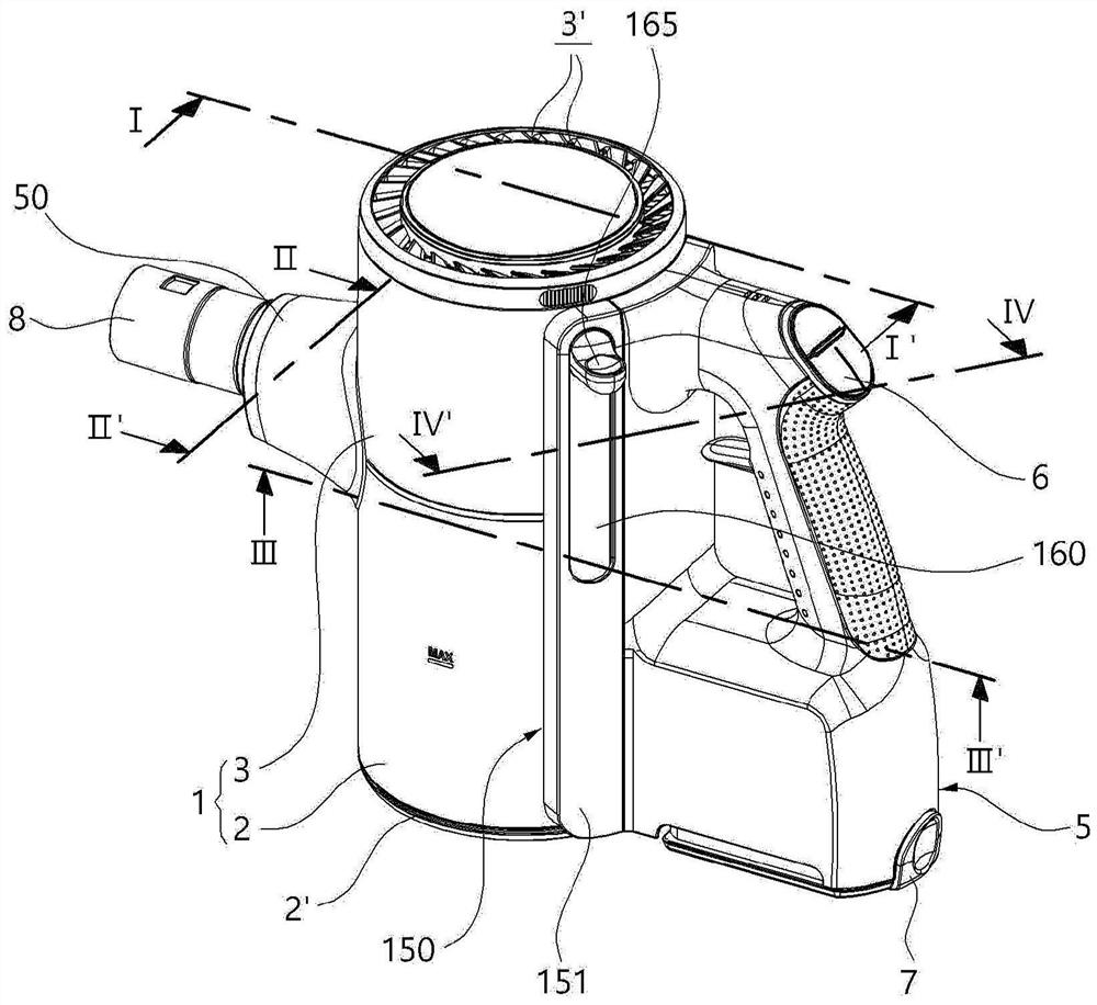
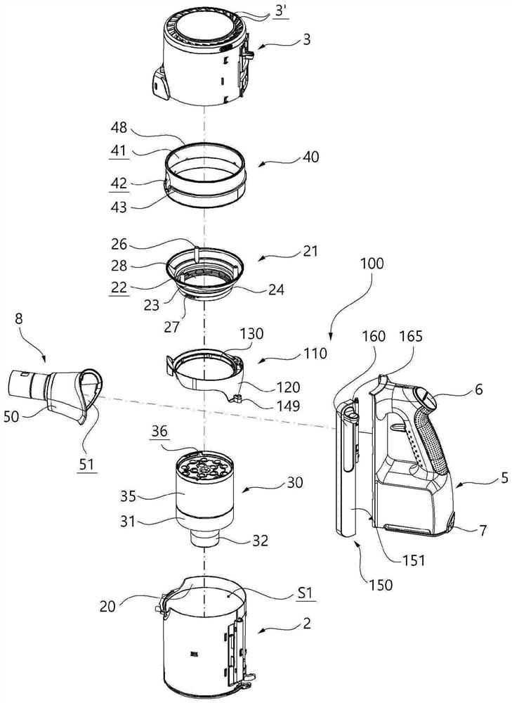
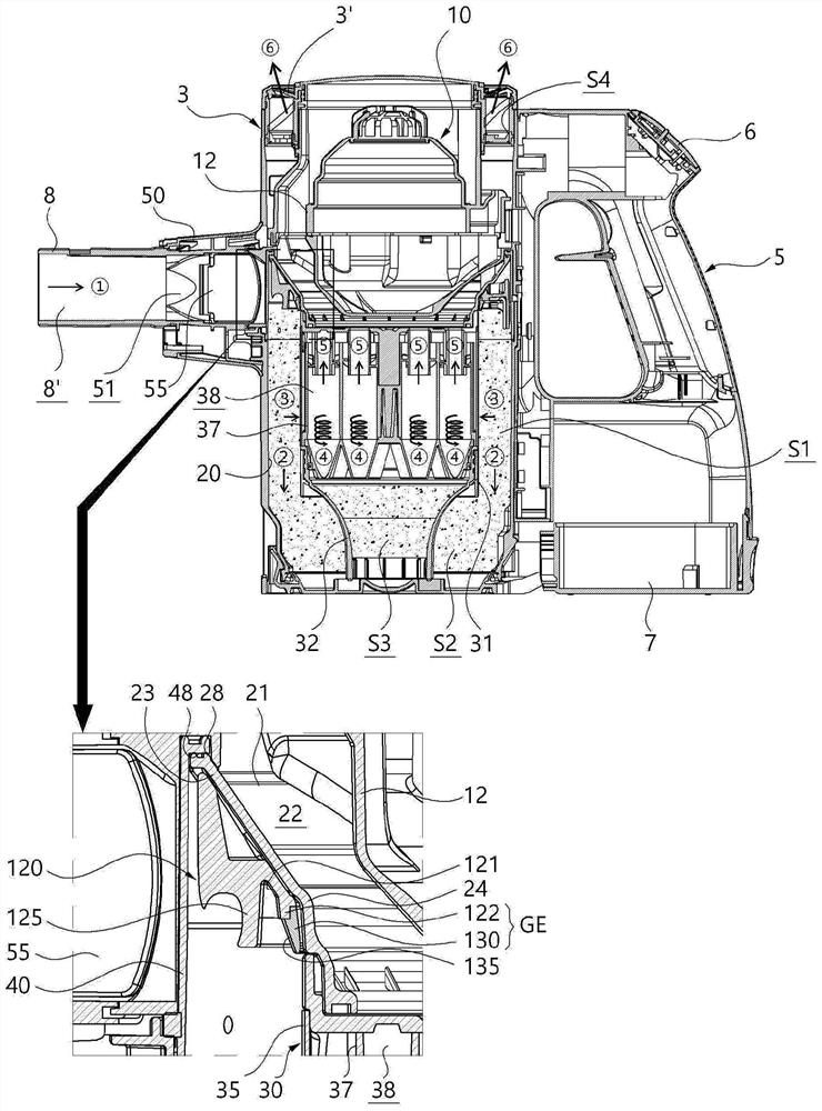
The invention relates to a cleaning machine. The present invention is provided with: a housing (1) provided with an intake port (8) into which air flows; a filter unit (30) provided in the internal space (S1) of the housing (1) and forming a dust collection space between the filter unit (30) and the inner surface (2) of the housing (1); and a cleaning unit (110) provided so as to surround the filter unit (30), the cleaning unit (110) moving up and down inside the dust collection space in conjunction with an operation unit (150), and forming a guide flow path (E) for guiding the flow of the sucked air by connecting at least a part of the cleaning unit (110) to an air suction path extending from the suction port (8) at an initial position. Furthermore, a guide fence (124B) is arranged along the outer edge of the cleaning unit (110), and the guide fence (124B) is opposite to the inner surface of the shell (1) and extends along the inner surface of the shell (1) to form the guide flow path (E). As a result, it is possible to block the path in which the sucked air moves along the gap (N) between the housing (1) and the cleaning unit (110) to the upper side of the cleaning unit (110) or to the connection portion (149) of the cleaning unit (110) and the operation unit (150).

Description

technical field [0001] The present invention relates to a cleaning machine, and more particularly, to a cleaning machine provided with a cleaning unit capable of compressing the dust inside the dust container when the dust container is not opened. Background technique [0002] A cleaning machine is a machine that performs cleaning by sucking in or wiping off dust or foreign matter in the area to be cleaned. Such cleaning machines are classified into manual cleaning machines that perform cleaning by directly moving the cleaning machine by a user, and automatic cleaning machines that perform cleaning by traveling by themselves. [0003] In addition, manual cleaners can be classified into tank cleaners, upright cleaners, hand-held cleaners, stick cleaners, and the like according to the shape of the cleaner. Among them, the hand-held vacuum cleaner includes a separation device for separating garbage and dust from the airflow. [0004] The above-mentioned separation apparatus i...

Claims


Application Information

Patent Timeline
Patent Type & Authority Applications(China)
IPC IPC(8): A47L5/24A47L9/02A47L9/10A47L9/32
CPCA47L5/24A47L9/16A47L9/20A47L9/1683A47L9/108A47L9/1641A47L9/165A47L9/322A47L9/1625A47L9/2884A47L9/149
Inventor 梁仁圭辛镇赫张大号柳炅浩
Owner LG ELECTRONICS INC
Learn More