Skin burn cleaning device
A technology for cleaning devices and skins, applied in the fields of enema/irrigator, medical science, surgery, etc., can solve the problem of inability to fix the irrigator, and achieve the effect of convenient cleaning
- Summary
- Abstract
- Description
- Claims
- Application Information
AI Technical Summary
Problems solved by technology
Method used
Image

Examples
Embodiment 1
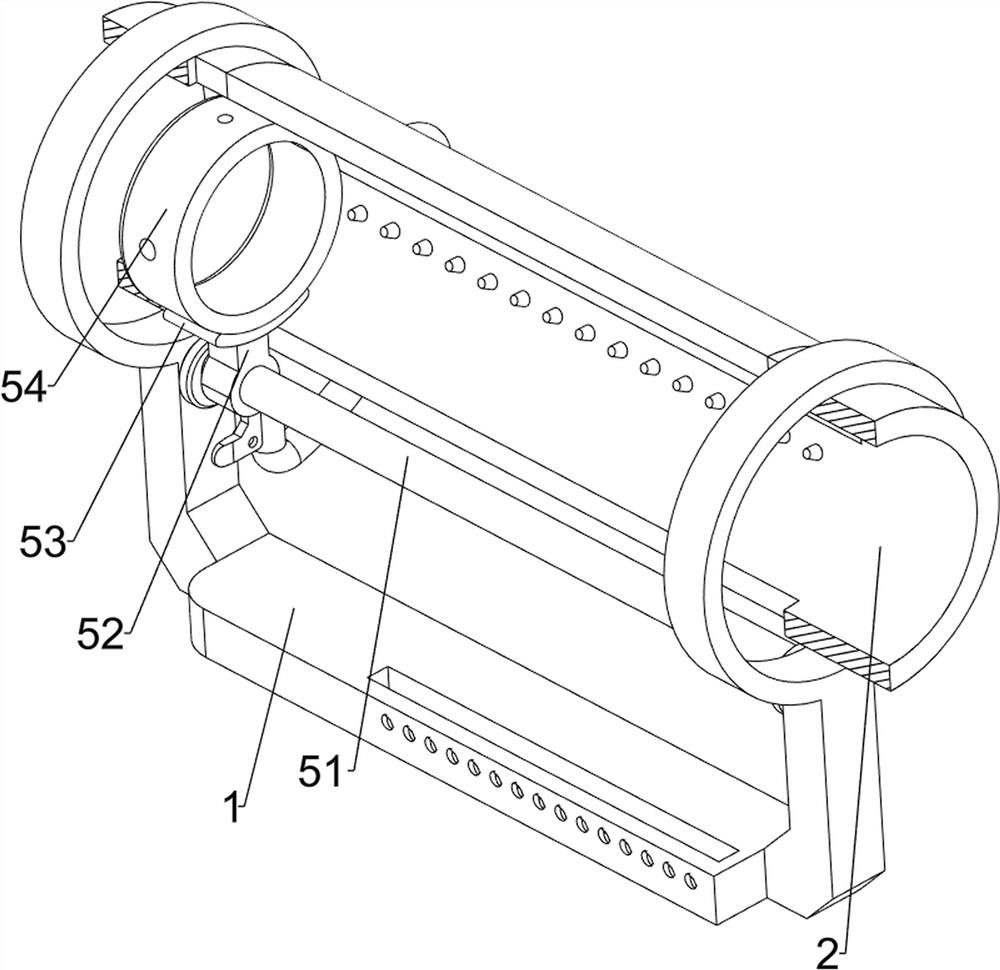
[0036] A device for washing skin burns, such as figure 1 , figure 2 , image 3 , Figure 4 , Figure 5 , Figure 6 , Figure 5 , Figure 9 , Figure 10 , Figure 11 , Figure 12 and Figure 14As shown, it includes a support frame 1, a limit barrel 2, a water inlet pipe 3, a nozzle 31, a cover mechanism 4, a fixing mechanism 5 and an automatic inflation mechanism 6, and the limit barrel 2 is fixed on the support frame 1 by bolts, and the limit barrel 2. A water inlet pipe 3 is fixedly connected to the front end of the lower left side, and a nozzle 31 is fixedly connected to the water inlet pipe 3 through bolts, and the nozzle 31 is located inside the limit bucket 2, and the outside of the limit bucket 2 is provided with a cover mechanism 4 and a support frame The middle part of 1 is provided with fixing mechanism 5, and the right end of support frame 1 top rear side is provided with automatic inflation mechanism 6.
[0037] like figure 1 and Figure 4 As shown, th...
Embodiment 2
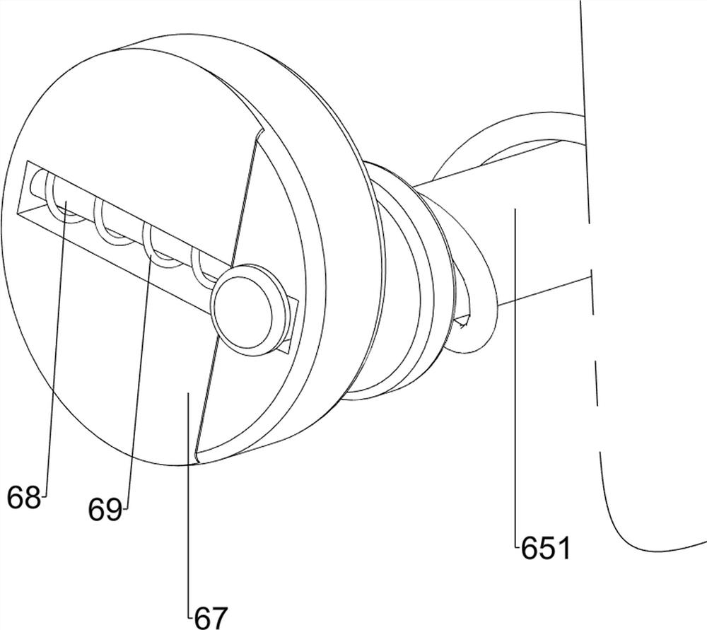
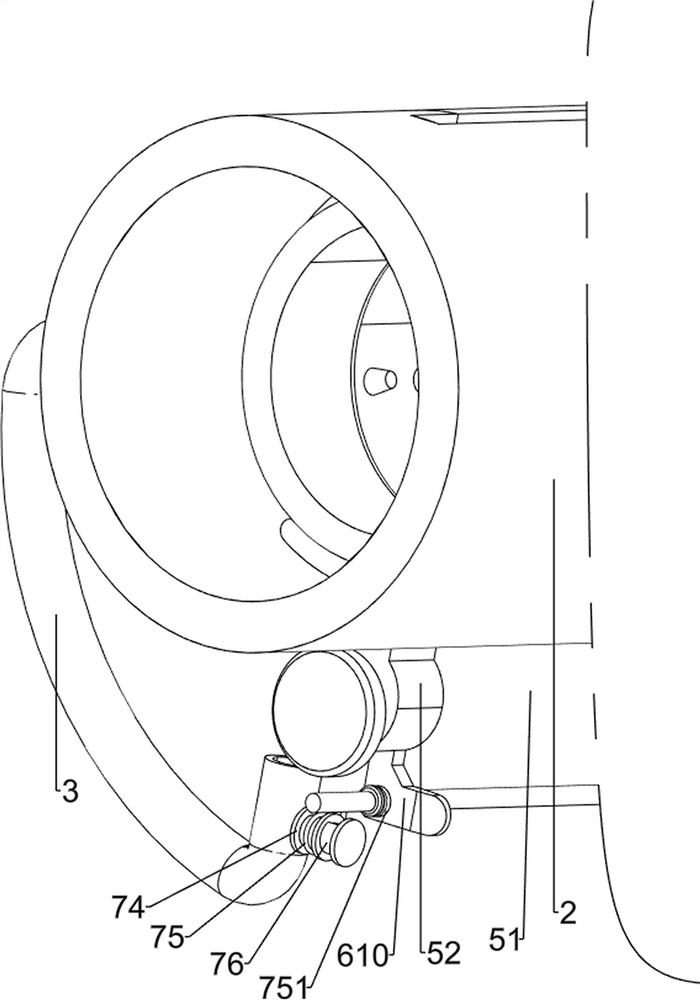
[0042] On the basis of Example 1, such as figure 1 , Figure 9 , Figure 10 and Figure 11 As shown, quantitative mechanism 7 is also included. Quantitative mechanism 7 includes limiting rod 71, blocking plate 72, connecting rod 73, winding wheel 74, wire rope 75, block 751 and scroll spring 76, and the middle part of support frame 1 Between the front and rear ends, the limit rod 71 is fixedly connected by bolts, and the limit rod 71 is positioned at the lower side of the rodless cylinder 51. The water inlet pipe 3 is connected with a connecting rod 73 in a rotational manner, and the connecting rod 73 is fixedly connected with a screw. Blocking plate 72, and blocking plate 72 is rotatably matched with water inlet pipe 3, and the right end of connecting rod 73 is fixedly connected with reel 74 by bolt, is wound with cord 75 on reel 74, has on the push block 610 and is provided with clamping block. 751 matching draw-in groove, is convenient to the quantitative cleaning of the...
Embodiment 3
[0045] On the basis of Example 2, such as figure 2 , Figure 12 and Figure 13 As shown, it also includes a ball float mechanism 8, the ball float mechanism 8 includes a hollow rod 81, a connecting plate 82, a third spring 83, an elastic rope 84 and a plastic ball 85, the inner side of the limit barrel 2 is fixed with a hollow Rod 81, the interior of hollow rod 81 is connected with connecting plate 82 slidingly, the third spring 83 is connected between connecting plate 82 and hollow rod 81, the bottom of connecting plate 82 is connected with elastic rope 84, the lower end of elastic rope 84 is fixed Connect with plastic ball 85.
[0046] In the process of stretching the skin-burned arm into the limit bucket 2, the plastic ball 85 can be held tightly. The ball 85 slides to the rear side, and the plastic ball 85 drives the elastic cord 84 to slide to the rear side. When the elastic cord 84 slides to the rear side, it can drive the connecting plate 82 to slide to the rear side....
PUM
 Abstract
Description
Claims
Application Information
 - R&D Engineer
- R&D Manager
- IP Professional
- Industry Leading Data Capabilities
- Powerful AI technology
- Patent DNA Extraction
Browse by: Latest US Patents, China's latest patents, Technical Efficacy Thesaurus, Application Domain, Technology Topic.
© 2024 PatSnap. All rights reserved.Legal|Privacy policy|Modern Slavery Act Transparency Statement|Sitemap