Scraper conveyor fault detection method and system and storage medium

A scraper conveyor and fault detection technology, which is applied to conveyor objects, conveyor control devices, transportation and packaging, etc., can solve problems such as expanding scraper conveyor failures, scraper conveyor failures, and complex working conditions. , to avoid further expansion of faults, save power consumption, and improve efficiency.

Pending Publication Date: 2022-05-31
SHENHUA SHENDONG COAL GRP +1
View PDF0 Cites 0 Cited by
  • Summary
  • Abstract
  • Description
  • Claims
  • Application Information

AI Technical Summary

Problems solved by technology

The scraper conveyor is widely used in mining machinery transportation, but due to the complex and harsh working conditions in the mine environment, the scraper conveyor is in the process of operation, due to reasons such as incomplete unloading, material impact, and large debris jamming. The scraper conveyor often fails
For example, if the scraper conveyor is not completely unloaded, large pieces of material or sundries will enter the sprocket support nest along with the chain, causing the chain to derail or the chain to be strung together; The links of the chain will be stretched to different degrees, resulting in different tightness of the chains on both sides; another example, large foreign objects and excessive wear will cause the chain or scraper to be blocked, resulting in excessive stretching of the chain or deformation of the scraper
When the scraper conveyor fails, the material conveying task cannot be completed normally. If the scraper conveyor continues to run, it will cause unnecessary consumption of electricity, and it may further expand the failure of the scraper conveyor.

Method used


Image

  • Scraper conveyor fault detection method and system and storage medium
  • Scraper conveyor fault detection method and system and storage medium
  • Scraper conveyor fault detection method and system and storage medium

Examples


Embodiment Construction

[0048] The preferred embodiments of the present application will be described below in conjunction with the accompanying drawings. It should be understood that the preferred embodiments described here are only used to illustrate and explain the present application, and are not intended to limit the present application.

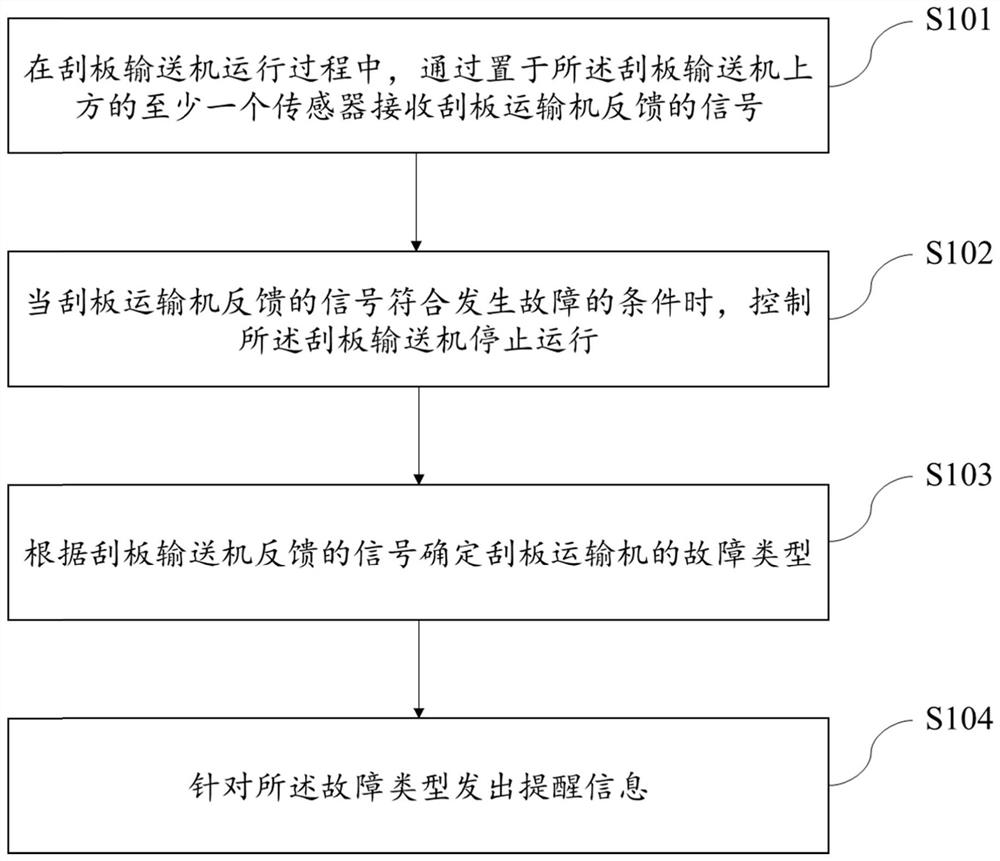
[0049] figure 1 It is a flow chart of a scraper conveyor fault detection method in an embodiment of the present application. This method can be used to detect the running status of the scraper conveyor in real time. When various faults are detected, it will stop in time and send an alarm information. like figure 1 As shown, the method can be implemented as the following steps S101-S104:

[0050] In step S101, during the operation of the scraper conveyor, a signal fed back by the scraper conveyor is received through at least one sensor placed above the scraper conveyor;

[0051] In step S102, when the signal fed back by the scraper conveyor meets the failure...


PUM


Abstract

The invention discloses a fault detection method, device and system for a scraper conveyor. The fault detection method, device and system are used for detecting whether the scraper conveyor breaks down or not in real time. The method comprises the steps that in the operation process of the scraper conveyor, signals fed back by the scraper conveyor are received through at least one sensor arranged above the scraper conveyor; when the signal fed back by the scraper conveyer meets the fault occurrence condition, the scraper conveyer is controlled to stop running; the fault type of the scraper conveyor is determined according to the signals fed back by the scraper conveyor; and sending reminding information for the fault type. By the adoption of the scheme, when the scraper conveyor breaks down, electricity consumption can be saved, and further expansion of the fault is avoided; meanwhile, the fault type can be judged according to the feedback signal, and a fault prompt is sent according to the fault type, so that a worker can conveniently know the fault type in advance, and the fault removal efficiency is improved.

Description

technical field [0001] The present application relates to the technical field of electrical detection of transportation equipment, in particular to a fault detection method, system and storage medium of a scraper conveyor. Background technique [0002] The scraper conveyor is a mechanical device that is driven by the scraper chain to move the scraper and transports bulk materials in the tank, including head wheels, tail wheels, middle tanks, transmission devices, etc. The scraper conveyor is widely used in mining machinery transportation, but due to the complex and harsh working conditions in the mine environment, the scraper conveyor is in the process of operation, due to reasons such as incomplete unloading, material impact, and large debris jamming. As a result, the scraper conveyor often fails. For example, if the scraper conveyor is not completely unloaded, large pieces of material or sundries will enter the sprocket support nest along with the chain, causing the chain...

Claims


Application Information

Patent Timeline
IPC IPC(8): B65G43/00B65G43/06
CPCB65G43/00B65G43/06
Inventor 马金立白富强艾婷
Owner SHENHUA SHENDONG COAL GRP
Why Eureka
Try Eureka