Efficient spring receiving device
A material receiving device and high-efficiency technology, applied in the field of spring processing, can solve problems such as slow transfer speed, complex spring transfer structure, spring dumping, etc.
- Summary
- Abstract
- Description
- Claims
- Application Information
AI Technical Summary
Problems solved by technology
Method used
Image

Examples
Embodiment 1
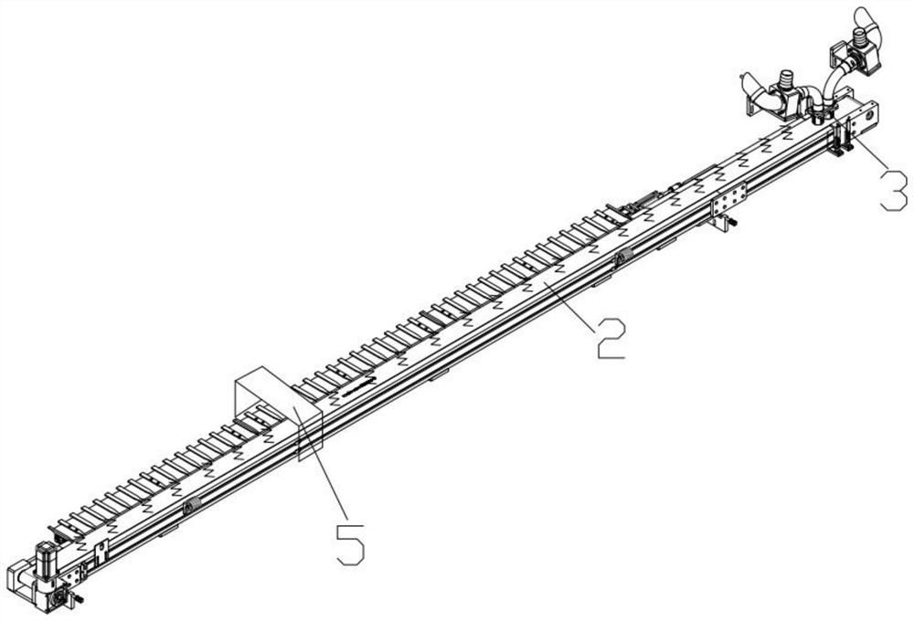
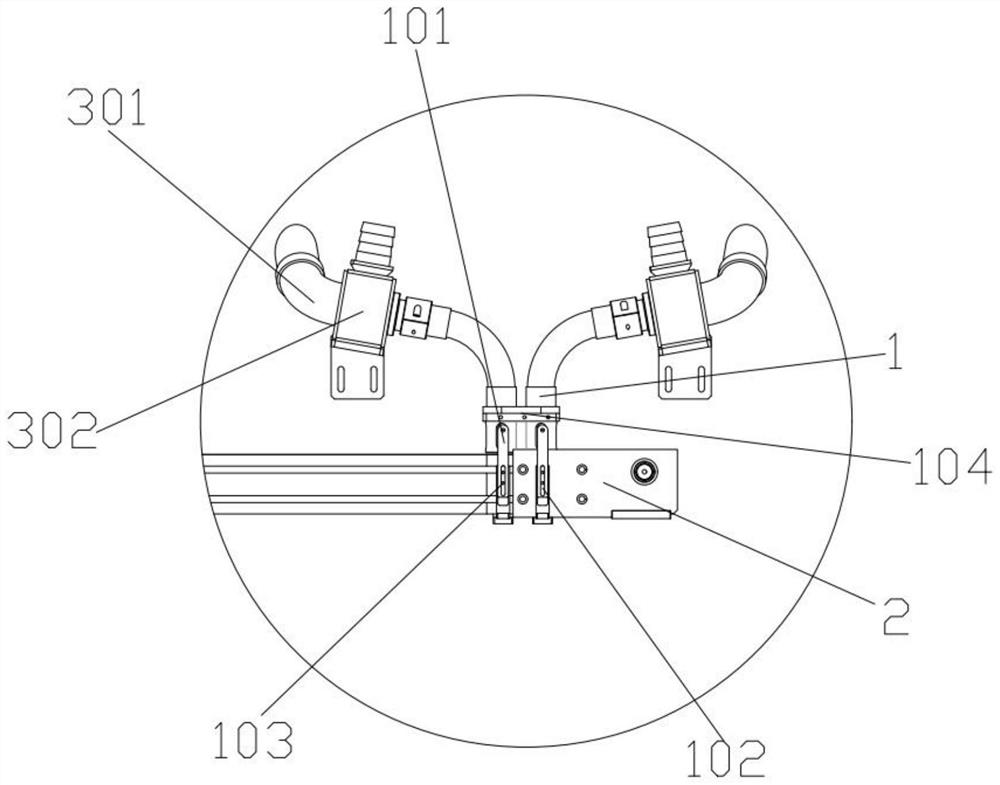
[0023] Embodiments of the present invention provide a high-efficiency spring material receiving device, such as Figure 1-4 As shown, it includes a high-efficiency material receiving mechanism 3, which is set correspondingly to the conveying mechanism 2, and the efficient material receiving mechanism 3 is used to transfer the spring to be processed to the conveying mechanism 2, and the high-efficiency material receiving mechanism 3 includes The transmission pipe 301 is connected to the protection block 1 , and the protection block 1 and the transmission pipe 301 are slidably connected. The transmission cavity in the transmission pipe 301 and the cavity in the protection block 1 are used to transmit the spring to be processed.
[0024] The number of the conveying pipe 301 and the protective material block 1 is any one or several, and the conveying pipe 301 corresponds to the protective material block 1 one by one, and the inlet end of the protective material block 1 and the inle...
Embodiment 2
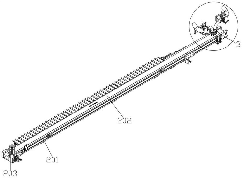
[0028] On the basis of above-mentioned embodiment 1, as Figure 1-4 As shown, the conveying mechanism 2 includes a transmission frame 201, a conveyor belt 202 is arranged inside the conveyor frame 201, a number of magnets are arranged at the bottom of the conveyor belt 202, and the conveyor belt 202 is transmitted through a number of conveyor pulleys, and the transmission frame 201 is far away from the high-efficiency A drive motor 203 is fixedly installed on one side of the receiving mechanism 3, and the drive motor 203 is fixedly connected to the conveyor pulley on the corresponding side;
[0029] The outlet end of the protective material block 1 is set correspondingly to the conveyor belt 202, the conveying pipe 301 is communicated with the air intake block 302, and the connection between the conveying pipe 301 and the air intake block 302 is provided with a deflector 304, the The intake block 302 communicates with the intake pipe 303, and the intake pipe 303 is connected w...
Embodiment 3
[0035] On the basis of Example 1, such as Figure 5-Figure 6 As shown, a cooling device is also included, and the cooling device cooperates with the conveying mechanism 2, and the cooling device includes:
[0036] Cooling shell 5, the middle part of the upper end of the cooling shell 5 is provided with an air intake hole 501 up and down, the middle part of the lower end of the cooling shell 5 is provided with a groove three 504, and the air intake hole 501 communicates with the third groove 504 , the conveying mechanism 2 passes through the groove three 504, a first cavity 502 is provided inside the left end of the cooling shell 5, and a second cavity 503 is provided inside the left end of the cooling shell 5;
[0037] The air intake shell 6, the air intake shell 6 is fixedly arranged inside the groove three 504, the upper end of the air intake shell 6 is provided with an air intake cavity 603, and the lower end of the air intake shell 6 is provided with an air outlet cavity 6...
PUM
 Abstract
Description
Claims
Application Information
 - R&D
- Intellectual Property
- Life Sciences
- Materials
- Tech Scout
- Unparalleled Data Quality
- Higher Quality Content
- 60% Fewer Hallucinations
Browse by: Latest US Patents, China's latest patents, Technical Efficacy Thesaurus, Application Domain, Technology Topic, Popular Technical Reports.
© 2025 PatSnap. All rights reserved.Legal|Privacy policy|Modern Slavery Act Transparency Statement|Sitemap|About US| Contact US: help@patsnap.com