
Self-adaptive scene marking high-precision geographic information calculation method

A technology of geographic information and calculation methods, applied in calculation, image data processing, 3D image processing, etc., can solve problems such as increased target calculation errors, inapplicable pictures taken at daily angles, and high requirements for two-dimensional directional map pictures

Pending Publication Date: 2022-05-31
ZHEJIANG SUPCON INFORMATION TECH CO LTD
View PDF1 Cites 1 Cited by
  • Summary
  • Abstract
  • Description
  • Claims
  • Application Information

AI Technical Summary

Problems solved by technology

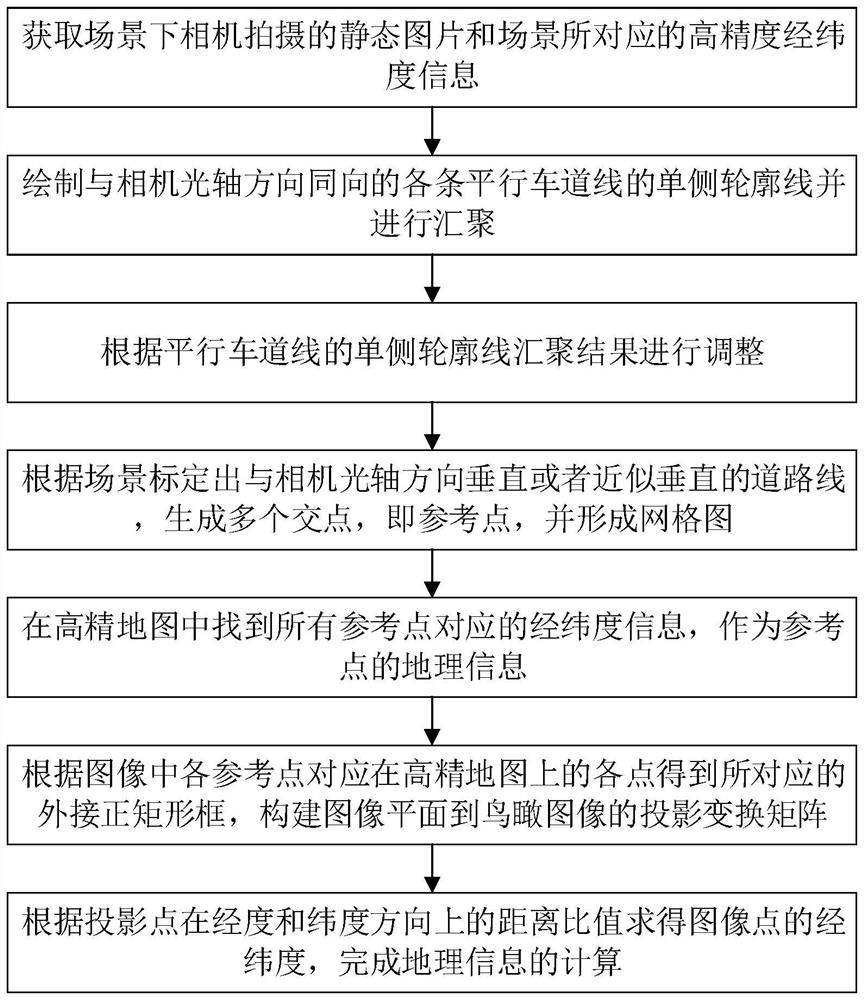
[0004] The present invention mainly solves the technical problem that the original technical solution has high requirements for two-dimensional directional map pictures and cannot be applied to pictures taken at daily angles, and provides a high-precision geographic information calculation method for adaptive scene marking, by calibrating the road surface in the reference image The position and orientation of lane lines and auxiliary lane lines divide the picture into multiple non-overlapping quadrilateral grids, and then determine the position of a specific object in the picture and the grid to which it belongs, so as to obtain the latitude and longitude information of the object. , in order to solve the problem of increased calculation error of long-distance targets caused by the perspective relationship, the calculation error is controlled within 1m through self-adaptive and precise positioning of reference points in the early stage of scene calibration

Method used


Image

  • Self-adaptive scene marking high-precision geographic information calculation method
  • Self-adaptive scene marking high-precision geographic information calculation method
  • Self-adaptive scene marking high-precision geographic information calculation method

Examples


Embodiment Construction

[0043] The technical solutions of the present invention will be further described in detail below through embodiments and in conjunction with the accompanying drawings. Embodiment: a high-precision geographic information calculation method for adaptive scene marking of this embodiment, such as figure 1 shown, including the following steps:

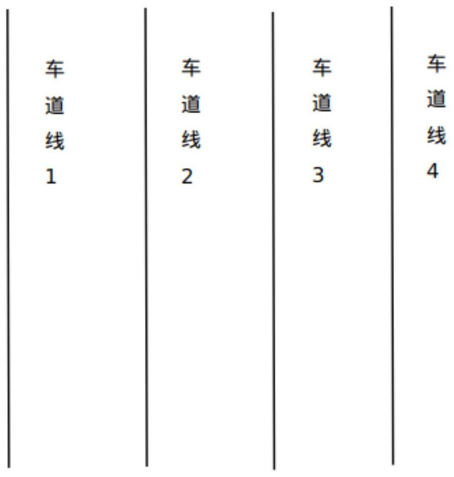
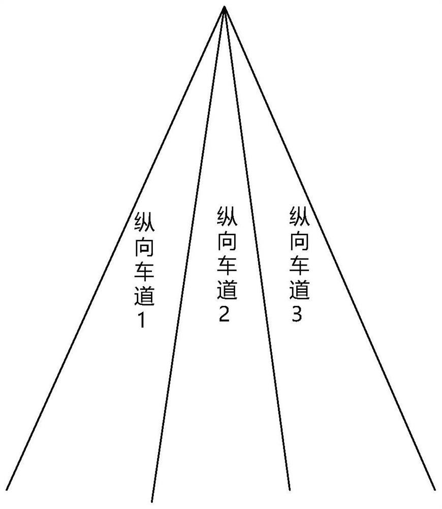
[0044] S1 acquires a still picture captured by a camera in a scene and high-precision latitude and longitude information corresponding to the scene. Step S1 obtains the static picture taken by the camera in the scene, and marks three or more parallel lane lines or at least two points on the unilateral contour of the line parallel to the lane line, and at least two points on the unilateral contour of the line parallel to the lane line, and the non-parallel to the lane line by manual method or detection algorithm detection method. , but conveniently marked straight lines in the image, such as figure 2 shown.

[0045] S2 draws the unilate...


PUM


Abstract

The invention discloses a high-precision geographic information calculation method for self-adaptive scene marking. The method comprises the following steps: acquiring a static picture shot by a camera in a scene and high-precision longitude and latitude information corresponding to the scene; drawing single-side contour lines of the parallel lane lines in the same direction as the optical axis direction of the camera, and converging the single-side contour lines; adjusting according to a single-side contour line convergence result of the parallel lane lines; road lines perpendicular to or approximately perpendicular to the optical axis direction of the camera are calibrated according to the scene, a plurality of intersection points, namely reference points, are generated, and a grid chart is formed; longitude and latitude information corresponding to all the reference points is found in the high-precision map and serves as geographic information of the reference points; obtaining a corresponding external rectangular frame according to each point on the high-precision map corresponding to each reference point in the image, and constructing a projection transformation matrix from the image plane to the aerial view image; and calculating the longitude and latitude of the image point according to the distance ratio of the projection point in the longitude and latitude directions, thereby completing the calculation of the geographic information.

Description

technical field [0001] The invention relates to the technical field of geographic location positioning, in particular to a high-precision geographic information calculation method for adaptive scene marking. Background technique [0002] Some data show that remote sensing technology and lidar technology have developed rapidly, and they can obtain large-scale urban surface information, provide data sources for urban research, and are widely used in urban street landscape research. However, the surface landscape images obtained by remote sensing technology are from a top-down perspective, and their two-dimensional characteristics cannot be prepared to express the landscape at the street level, nor can the surface landscape be displayed from a human perspective. Although lidar technology obtains the three-dimensional coordinates of ground objects and displays them in the form of discrete points, it overcomes the two-dimensional defects of remote sensing images, but the optical ...

Claims


Application Information

Patent Timeline
IPC IPC(8): G06T3/00G06T15/20G06T17/05G01C21/36
CPCG06T15/205G06T17/05G01C21/3676G06T3/08
Inventor 徐梦吴劲峰张巧焕陈瑞生宋腾飞蒋栋奇
Owner ZHEJIANG SUPCON INFORMATION TECH CO LTD
Learn More