
Grabbing device for mechanical manufacturing

A grasping device and mechanical manufacturing technology, applied in the field of grasping devices for mechanical manufacturing, can solve the problems of poor flexibility between structures, poor coherence between structures, and inability to tightly fit and grasp accessories, and achieve installation and Easy to disassemble, reduce impact wear and improve flexibility

Inactive Publication Date: 2022-06-03
南通杰蕾机械有限公司
View PDF6 Cites 0 Cited by
  • Summary
  • Abstract
  • Description
  • Claims
  • Application Information

AI Technical Summary

Problems solved by technology

[0004] In order to solve the above-mentioned technical problems, the present invention provides a grabbing device for mechanical manufacturing, which solves the problem that the existing grabbing device for mechanical manufacturing cannot use the left and right bouncing effect of the spring to deflect and unload the impact force, and does not have vertical The shock absorption and buffering function in the direction, the flexibility between the structures is poor, the continuity between the structures is not smooth, it is impossible to closely fit and grasp the accessories of different structural shapes, it does not have the function of anti-shock and anti-falling of accessories, and it is impossible to adjust the accessories. Problems with smooth gripping and transport

Method used


Image

  • Grabbing device for mechanical manufacturing
  • Grabbing device for mechanical manufacturing
  • Grabbing device for mechanical manufacturing

Examples


Embodiment 1

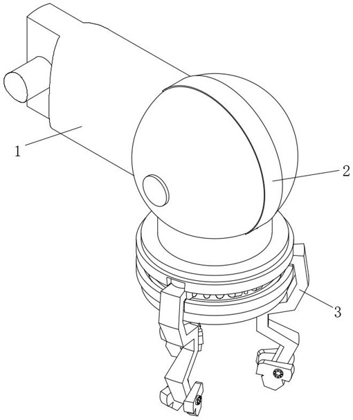
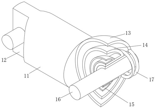
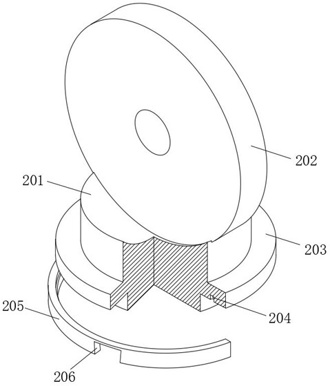
like Figure 1-Figure 6As shown, the present invention provides a technical solution: comprising an assembly mechanism 1, a hoisting assembly 2 is installed at the front end of the assembly mechanism 1, and a grabbing mechanism 3 is installed at the lower end of the hoisting assembly 2; the assembly mechanism 1 includes a short assembly rod 11, the short assembly rod 11 The rear end surface is provided with a clamping groove 12 for convenient assembly, the front end of the short assembly rod 11 is installed with an outer spherical shell 13, the inner side of the outer spherical shell 13 is installed with an air pressure cover 14, and the air pressure cover 14 is installed between the outer spherical shell 13 and the air pressure cover 14. There is a built-in spring 17, and the air pressure cover 14 is elastically installed with the outer spherical shell 13 through the built-in spring 17; the suction cup cover 15 is installed on the inner side of the air pressure cover 14, and th...

Embodiment 2

like Figure 5-Figure 6 As shown, the gripping mechanism 3 includes a hook 31, the upper surface of the hook 31 is fixedly connected with a connecting ball 32, the lower end of the hook 31 is fixedly connected with a bow plate 33, and the lower end of the bow plate 33 is installed with a side clamping block 34 The side clamp block 34 is installed with a positioning ring 35 on the side away from the bow plate 33, and the rear end surface of the positioning ring 35 is installed with a positioning insert 36 in a circular array, and the side clamp block 34 is fixed on one side of the bow plate 33. A shaft rod 37 is connected, an alignment hole 38 is opened on the surface of the bow plate 33, and the side clamp blocks 34 are symmetrically installed on the front and rear sides of the bow plate 33; The alignment hole 38 is combined and installed with the bow plate 33, wherein the side clamp block 34 is rotated and installed with the bow plate 33 through the shaft rod 37, and the surfa...


PUM


Abstract

The grabbing device for mechanical manufacturing comprises an assembling mechanism, a hoisting assembly is installed at the front end of the assembling mechanism, a grabbing mechanism is installed at the lower end of the hoisting assembly, a steel ring, a hook claw and a short connection column are installed in a combined mode through a plug pin thin rod, meanwhile, connecting balls matched with clamping springs are effectively isolated from one another, and the clamping springs are clamped to the clamping springs; mutual interference when the tightness degree between the clamping spring and the connecting ball is adjusted is avoided, the elastic extrusion strength of the clamping spring on the two sides of the connecting ball can be changed by rotating the clamping blocks on the two sides of the connecting ball, and through the operation, a movable range is provided for the hook claw to shake around the arc with the short connecting column as the center on the horizontal plane; and in combination with the left-right springing effect of the spring, the impact of external force on the accessory is unloaded through rotation of a certain amplitude.

Description

technical field [0001] The present invention relates to the technical field of machinery manufacturing, in particular to a grasping device for machinery manufacturing. Background technique [0002] Machinery manufacturing refers to the industrial sector engaged in the production of various power machinery, hoisting and transporting machinery, chemical machinery, textile machinery, machine tools, tools, instruments, meters and other mechanical equipment; machinery manufacturing provides technical equipment for the entire national economy, among which , The grasping device involved in the mechanical manufacturing process provides convenience for the staff to handle large parts and accessories, and avoids the direct handling of manpower, resulting in low work efficiency, damage to spare parts, and injuries to workers. [0003] The existing grasping device for machine manufacturing cannot use the left and right bouncing effect of the spring to deflect and unload the impact force...

Claims


Application Information

Patent Timeline
Patent Type & Authority Applications(China)
IPC IPC(8): B65G47/90
CPCB65G47/90
Inventor 张杰
Owner 南通杰蕾机械有限公司
Learn More