Blade structure, gas compressor and gas compressor control method

A technology of blade structure and control method, applied in pump control, machine/engine, mechanical equipment, etc., can solve the problems of impeller instability, inability to function, mixing, etc., to change the flow direction and eliminate tip leakage flow effect

Active Publication Date: 2022-06-03
BEIHANG UNIV
View PDF14 Cites 0 Cited by
  • Summary
  • Abstract
  • Description
  • Claims
  • Application Information

AI Technical Summary

Problems solved by technology

On the one hand, the tip leakage flow is different from the mainstream flow, so it will be mixed with the mainstream flow, resulting in a certain loss of turbine efficiency; on the other hand, a large number of studies have shown that when the turbine works at a small flow point, it can produce more High pressure ratio, but also with stronger leakage flow
When the leakage flow is close to the frontal line of the rotor, most of the cases will induce the instability of the turbine. At this time, the turbine cannot continue to work stably, and may even cause a major safety accident
The publication number is CN107061363A, and the name is a Chinese invention patent application for a blade top structure used to suppress the leakage flow of the compressor blade tip. The blade tip flow is suppressed by slotting on the blade tip of the blade, but there is a technical problem that it cannot be self-adaptive. , that is, the opened groove can only work effectively under specific working conditions, once it deviates from the preset working conditions, it will not be effective

Method used


Image

  • Blade structure, gas compressor and gas compressor control method
  • Blade structure, gas compressor and gas compressor control method
  • Blade structure, gas compressor and gas compressor control method

Examples


Embodiment Construction

[0030] The present invention will be further described in detail below with reference to the accompanying drawings and embodiments. It should be understood that the specific embodiments described herein are only used to explain the related content, but not to limit the present invention. In addition, it should be noted that, for the convenience of description, only the parts related to the present invention are shown in the drawings.

[0031] It should be noted that the embodiments of the present invention and the features of the embodiments may be combined with each other without conflict. The present invention will be described in detail below with reference to the accompanying drawings and in conjunction with the embodiments.

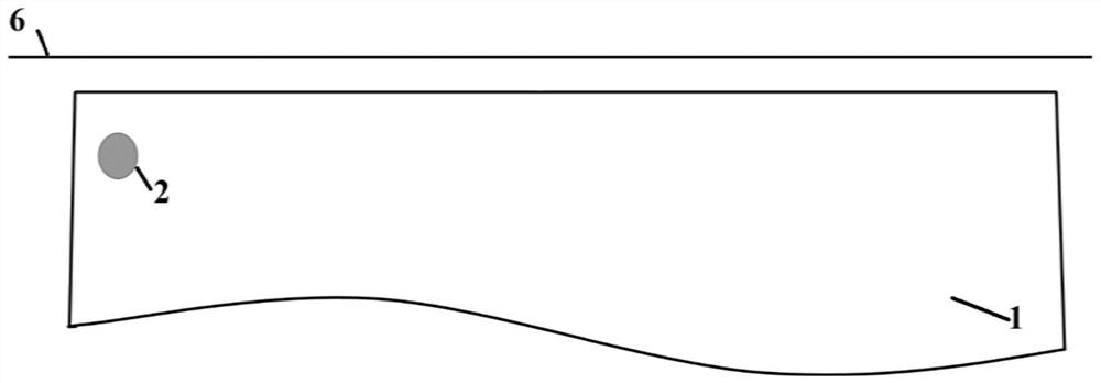
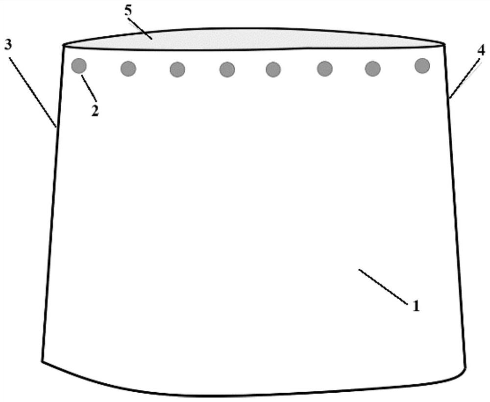
[0032] According to the first embodiment of the present invention, as figure 1 As shown, a blade structure is provided, including a blade 1 and a wall surface 6 that rotates relatively with the blade 1, and a first gap is provided between the blade...


PUM


Abstract

The invention provides a blade structure, a gas compressor with the blade structure and a control method for controlling the gas compressor, the blade structure comprises a blade and a wall surface rotating relative to the blade, and a first gap is formed between a blade top of the blade and the wall surface; each blade is provided with a windward first front edge and a first rear edge opposite to the first front edge; the blade top is provided with a plurality of flow guiding devices used for controlling leakage flow of the blade top, the flow guiding devices are distributed in the direction from the first front edge of the blade to the first rear edge of the blade, and when the flow guiding devices are in the first working state, the flow guiding devices are in the second working state. And a second gap smaller than the first gap is formed between at least one part of the flow guide device and the wall surface.

Description

technical field [0001] The invention relates to the technical field of impeller machinery, in particular to a blade structure, a compressor and a compressor control method. Background technique [0002] In the field of turbomachinery, especially for components such as fans / compressors with a certain supercharging function, work is performed on the flowing fluid (gas or liquid) through the cooperation of the rotor and the stator to increase the pressure ratio of the fluid; both the stator and the rotor include blades . Under normal circumstances, in order to avoid scratching, there will be a certain gap between the tip of the blade and the wall of the casing, which is the tip gap. During operation, due to the rotation of the rotor blades doing work on the fluid, the pressure on both sides of the blade is different. Driven by this part of the pressure difference, the fluid will flow through the tip gap, and this part of the flow is called tip leakage flow. Studies have shown...

Claims


Application Information

Patent Timeline
Patent Type & Authority Applications(China)
IPC IPC(8): F04D29/38F04D29/54F04D19/00F04D27/00
CPCF04D29/384F04D29/388F04D29/542F04D19/00F04D27/00F04D27/001Y02E10/72
Inventor 孙大坤李佳王宇晴董旭孙晓峰
Owner BEIHANG UNIV
Why Eureka
Try Eureka