Energy storage power supply fire extinguishing system and control method thereof

A technology of energy storage power supply and fire protection system, applied in the field of energy storage, can solve the problems of increased losses, unfavorable arrangement of energy storage batteries, and increased maintenance costs, and achieves the effect of increasing reserves

Pending Publication Date: 2022-06-07
启东沃太新能源有限公司
View PDF0 Cites 2 Cited by
  • Summary
  • Abstract
  • Description
  • Claims
  • Application Information

AI Technical Summary

Problems solved by technology

[0003] The current fire-fighting system is mainly for the whole cabin or a single cluster. In this way, the fire-fighting fluid will be sprayed on the normal battery, causing damage to the normal battery, and it may need to be replaced during maintenance, which greatly increases The maintenance cost is reduced; for the fire fighting system of the whole cabin, the fire fighting bottle is a large bottle, and the water pump transports the fire fighting liquid to each spraying point. Some spraying points are far away from the fire fighting bottle, and a long pipeline needs to be set up for transportation, which is not conducive to timely fire fighting operation At the same time, the volume occupied by the large bottle is relatively large, which is not conducive to the arrangement of the energy storage battery; for a single-cluster fire-fighting system, the fire-fighting bottle is a small bottle. May not be used enough, resulting in losses that will continue to increase over time

Method used


Image

  • Energy storage power supply fire extinguishing system and control method thereof
  • Energy storage power supply fire extinguishing system and control method thereof
  • Energy storage power supply fire extinguishing system and control method thereof

Examples


Embodiment Construction

[0027] The technical solutions of the present invention will be clearly and completely described below with reference to the accompanying drawings. Obviously, the described embodiments are a part of the embodiments of the present invention, but not all of the embodiments. Based on the embodiments of the present invention, all other embodiments obtained by those of ordinary skill in the art without creative efforts shall fall within the protection scope of the present invention.

[0028] In the description of the present invention, it should be noted that the terms "center", "upper", "lower", "left", "right", "vertical", "horizontal", "inner", "outer", etc. The indicated orientation or positional relationship is based on the orientation or positional relationship shown in the accompanying drawings, which is only for the convenience of describing the present invention and simplifying the description, rather than indicating or implying that the indicated device or element must hav...


PUM


Abstract

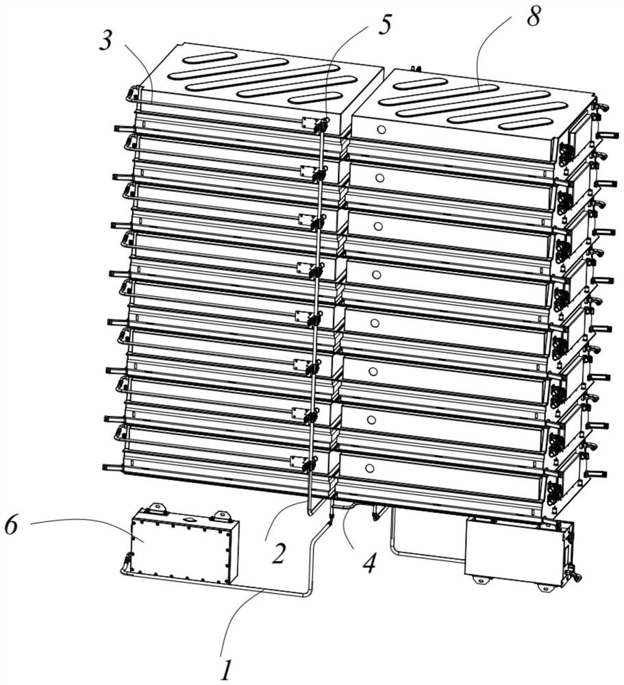
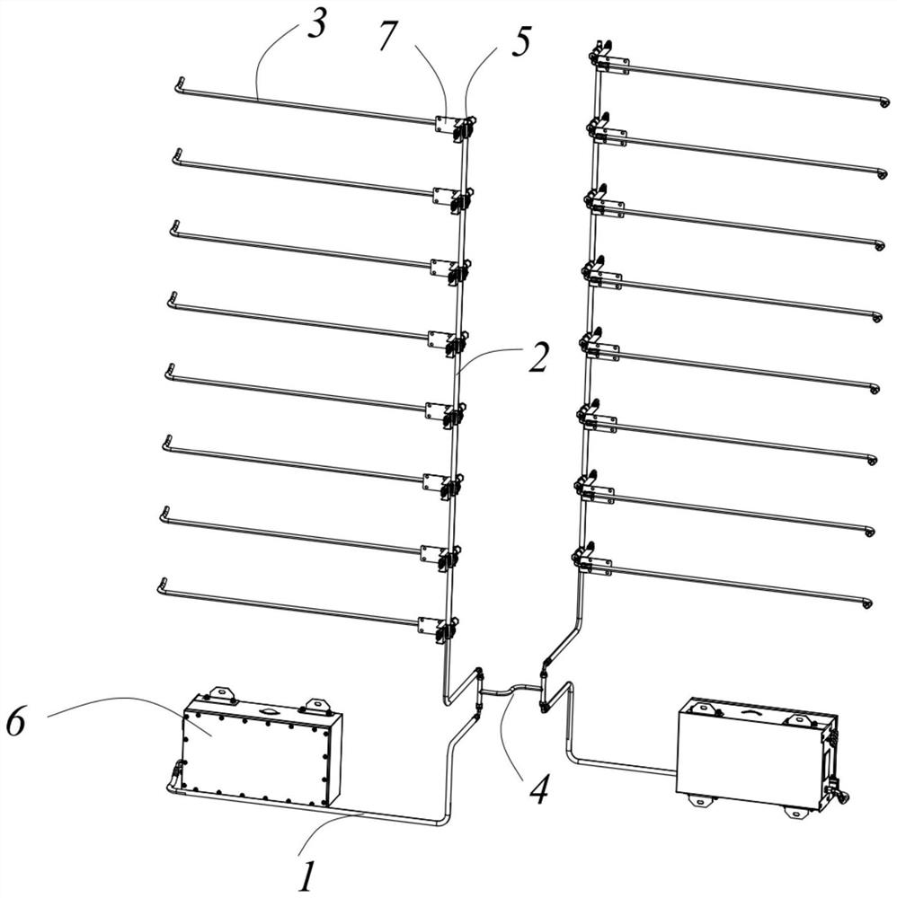
According to the energy storage power supply fire-fighting system and the control method thereof, a pipeline assembly is arranged between a fire-fighting host and batteries in a cluster of battery modules, the pipeline assembly comprises a first-stage pipeline, a second-stage pipeline and a plurality of third-stage pipelines, the first-stage pipeline is connected to the fire-fighting host, each third-stage pipeline is correspondingly connected to a single battery, and the second-stage pipeline is connected to the fire-fighting host; a branch control valve is arranged on the third-stage pipeline; dividing the plurality of clusters of battery modules into at least one group, wherein at least two clusters of battery modules are arranged in each group; the primary pipelines of the at least two fire-fighting hosts in each group are communicated through a connecting pipeline; through the arrangement of the branch control valves, accurate fire fighting and extinguishing can be carried out on batteries which are only subjected to thermal runaway, the storage amount of standby fire fighting liquid is increased by connecting other fire fighting main machines, and each fire fighting main machine serves as a main fire fighting bottle of the corresponding cluster battery module and also serves as a standby fire fighting bottle of other cluster battery modules; and by starting other clusters of fire-fighting main machines, it is guaranteed that fire-fighting liquid in the fire-fighting pipeline is always sufficient and has enough pressure.

Description

technical field [0001] The invention relates to the technical field of energy storage, in particular to a fire protection system of an energy storage power source and a control method thereof. Background technique [0002] In the energy storage technology industry, thermal runaway of batteries often occurs, which will make the temperature rise inside the battery and the current increase mutually promote each other, resulting in battery expansion or even explosion. For the thermal runaway phenomenon of the battery, a fire protection system is usually installed in the battery to prevent safety accidents. When the thermal runaway phenomenon occurs, the temperature is lowered by the fire protection system in time. [0003] The current fire protection system is mainly for the whole cabin or a single cluster. In this way, the fire fighting liquid will be sprayed on the normal battery, causing damage to the battery in normal use, and may need to be replaced during maintenance, ther...

Claims


Application Information

Patent Timeline
Patent Type & Authority Applications(China)
IPC IPC(8): A62C3/16A62C31/00A62C31/28A62C37/38
CPCA62C3/16A62C31/00A62C31/28A62C37/38Y02E60/10
Inventor 蔡青游峰汪承晔
Owner 启东沃太新能源有限公司
Why Eureka
Try Eureka