Double-vibrating-needle pitched roof control mechanism
A technology of control mechanism and spring needle, which achieves high stability and reliability, guaranteed injection molding quality, high mold release and buckle back effect
Active Publication Date: 2022-06-10
ZHEJIANG KAIHUA MOLDS
View PDF4 Cites 0 Cited by
- Summary
- Abstract
- Description
- Claims
- Application Information
AI Technical Summary
Problems solved by technology
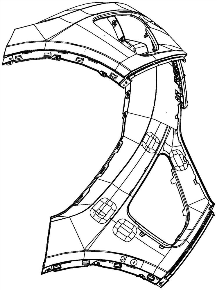
Its disadvantages are: for long arc-shaped injection molding products, when the inclined top is ejected, it is pushed on one side, and a slider is set inside the inclined top. The arc surface structure of the injection molded product between the slider and the inclined top needs Only multiple pins can ensure the limit, but the combined use of multiple pins at different angles will cause positional interference between the pins, and they cannot be retracted at the same time; and the use of multiple pins at the same angle will cause elasticity to the product. The limit ability of the structure is poor, so the processing quality and ejection efficiency cannot be taken into account when the elongated arc surface structure is manufactured with the inclined roof.
Method used
View moreImage
Smart ImageViewing Examples
Examples
Embodiment
Login to View More PUM
 Abstract
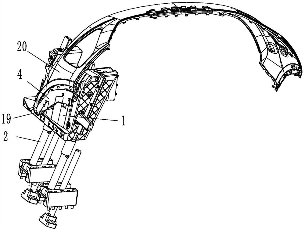
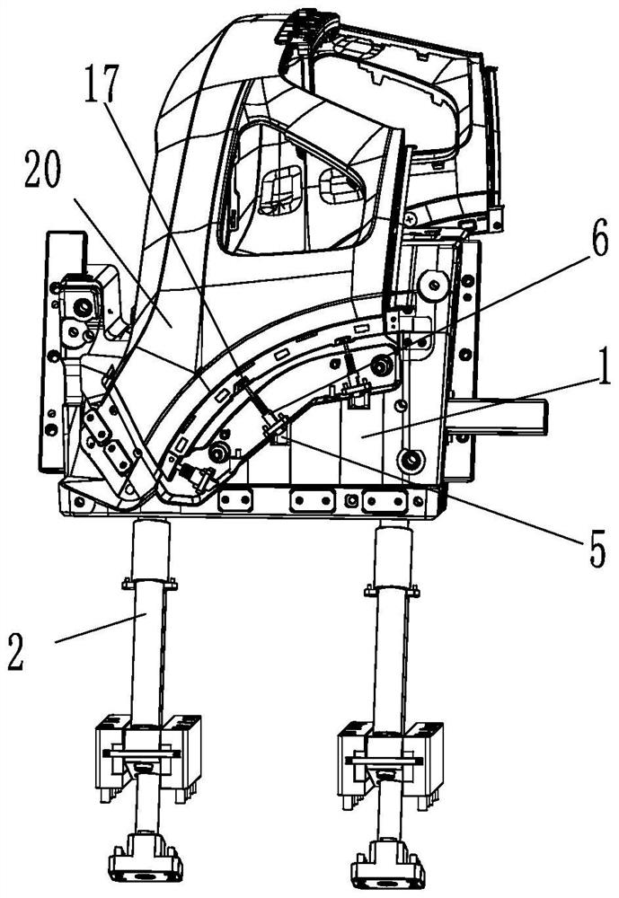
The invention discloses a double-elastic-needle pitched roof control mechanism which comprises a pitched roof head, a mold cavity is formed in the upper end of the pitched roof head, a push block is arranged in the mold cavity, a first elastic needle is arranged in the pitched roof head, and a second elastic needle abutting against the head of the first elastic needle is arranged in the push block. The ejection mechanism has the advantages that the inclined ejector is ejected out and retreats, the ejection position of the push block is fixed, when the inclined ejector is ejected out, the first elastic needle moves downwards, the second elastic needle retreats after the first elastic needle moves, reverse buckle retreating is achieved, then the inclined ejector can continue to be ejected out, the double-elastic-needle structure is arranged in a series connection mode, the counterpoint synergistic effect can be achieved, and the segmented secondary ejection effect is achieved; and the mold has higher demolding and reverse buckle withdrawing functions.
Description
technical field [0001] The present application relates to the technical field of a slanted ejector mechanism, in particular to a control mechanism for a slanted ejector with double ejectors. Background technique [0002] Injection molding is a tool for producing plastic products; it is also a tool for giving plastic products a complete structure and precise dimensions. Injection molding is a processing method used in mass production of certain complex-shaped parts. The injection molding machine injects into the mold cavity under high pressure, and after cooling and solidifying, the molded product is obtained. Existing injection molds generally use an inclined ejector mechanism to eject products when they are injecting products with undercuts. However, when some injection molded parts with undercuts are demolded, the undercuts may stick to the inclined roof. As the demoulding progresses, the inclined roof will retreat, and the undercuts will be deformed. In severe cases, the...
Claims
Login to View More Application Information
Patent Timeline
 Patent Type & Authority Applications(China)
IPC IPC(8): B29C45/44
CPCB29C45/4435
Inventor 梁正华梁凯王华良林连明
Owner ZHEJIANG KAIHUA MOLDS
Features
- R&D
- Intellectual Property
- Life Sciences
- Materials
- Tech Scout
- Unparalleled Data Quality
- Higher Quality Content
- 60% Fewer Hallucinations
Learn More Browse by: Latest US Patents, China's latest patents, Technical Efficacy Thesaurus, Application Domain, Technology Topic, Popular Technical Reports.
© 2025 PatSnap. All rights reserved.Legal|Privacy policy|Modern Slavery Act Transparency Statement|Sitemap|About US| Contact US: help@patsnap.com


