
Electrically-controlled brake test bench

A test bench, electronically controlled braking technology, applied in vehicle testing, machine/structural component testing, measuring devices, etc., to achieve the effects of low cost, simple hardware environment, and low modification cost

Inactive Publication Date: 2022-06-10
CHONGQING CHANGAN AUTOMOBILE CO LTD
View PDF10 Cites 0 Cited by
  • Summary
  • Abstract
  • Description
  • Claims
  • Application Information

AI Technical Summary

Problems solved by technology

(1) The requirements for the hardware electrical environment and the vehicle communication environment are high, the integration technology of the test bench is difficult, and the cost of the bench construction is high (the cost of a set of HIL bench is in the tens of millions)
[0003] (2) The platform has poor adaptability to different projects, and the restructuring is difficult and the cycle is long

Method used

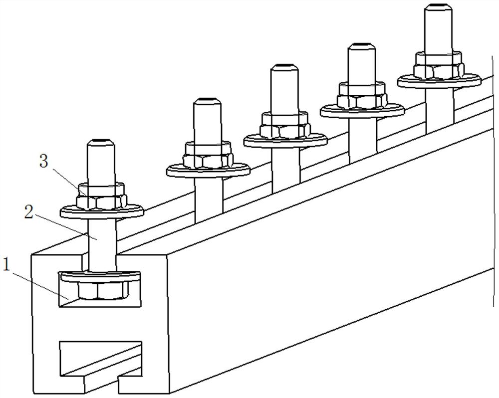
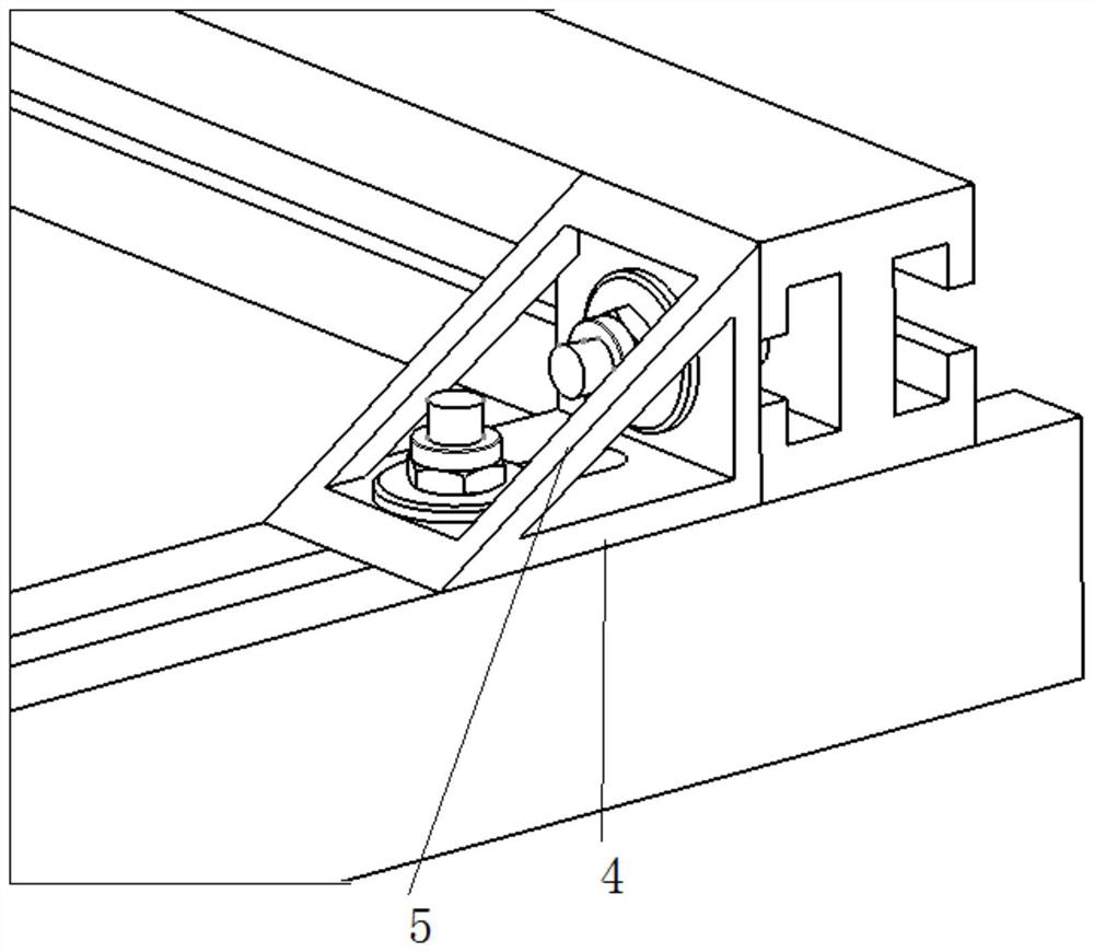

Image

  • Electrically-controlled brake test bench
  • Electrically-controlled brake test bench
  • Electrically-controlled brake test bench

Examples


Embodiment Construction

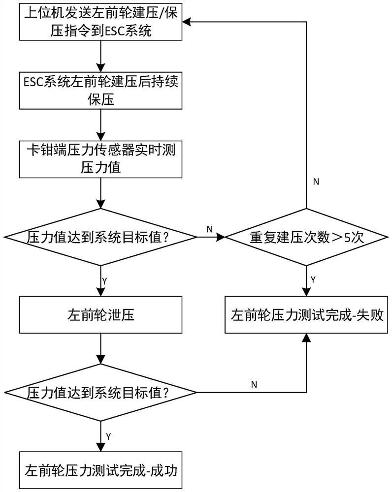
[0025] If the locked target pressure is reached within this pressure buildup cycle, the system will continue to enter the pressure hold phase within the command interval time. When the upper computer sends a pressure release command, the ESC system closes the liquid inlet valve and opens the liquid outlet valve according to the process, and the pressure in the ESC system is quickly released.

[0026] The pressure sensor feeds back the system pressure value in real time. After a fixed time after the pressure relief command is issued, if the pressure drops below the threshold value, the pressure relief is completed, otherwise the pressure relief fails.

[0027] After all the above processes are completed, the ESC system pressure building capability test link is completed. In the follow-up, complete the system pressure building ability test of other rounds in the order of left front-right front-left rear-right rear.


PUM


Abstract

The invention discloses an electrically-controlled brake test bench, which comprises a mechanical bench, a pressure sensor, a power supply module, a CAN communication module and an upper computer, a brake system is arranged on the mechanical rack and comprises a brake belt vacuum booster assembly, an ESC system, a brake hard pipe, a brake connecting hose, calipers, a brake disc, an electronic hand brake and a pressure sensor. The pressure sensor is installed on a tee joint of a caliper liquid inlet and used for conducting closed-loop monitoring on the actual pressure of the wheel end and feeding the actual pressure back to the upper computer to conduct closed-loop pressure buildup control testing. The upper computer is in communication connection with a braking system through the CAN communication module, and the upper computer is used for simulating a whole vehicle communication environment interacting with braking electric control, processing wheel end pressure in a closed loop mode and driving an ESC system to establish braking pressure. According to the invention, partial function response and voltage buildup capability of the ESC can be tested on a rack based on a whole vehicle simulation communication environment.

Description

technical field [0001] The invention belongs to the technical field of test stands, and in particular relates to an electric control brake test stand. Background technique [0002] The brake test bench is a test bench that includes a complete set of brake system components (such as: brake pedal, master cylinder with booster assembly, ESC (Electric Stability Control), soft and hard oil pipes, calipers and other fasteners) shelf. In the prior art, most focus on the design of the construction and fastening methods of the mechanical bench (such as a vehicle braking bench test device disclosed in CN201920777486.8), lacking the design of the test bench related to the electronic control system. The purely mechanical test bench mainly tests the basic brake components (for example, the PV curve of the brake caliper, the brake pedal force, the performance of the vacuum booster, etc.), the electronic stability control system and the integrated electronic power booster system, etc. Th...

Claims


Application Information

Patent Timeline
Patent Type & Authority Applications(China)
IPC IPC(8): G01M17/007
CPCG01M17/007
Inventor 王高瑞乔斌刘佳勇张磊光张鹏飞
Owner CHONGQING CHANGAN AUTOMOBILE CO LTD
Learn More