

Multi-power supply switching circuit
A technology of power supply switching and multi-power supply, which is applied in the direction of circuit devices, emergency power supply arrangements, electrical components, etc.
Pending Publication Date: 2022-06-10
UNIV OF ELECTRONICS SCI & TECH OF CHINA
View PDF4 Cites 1 Cited by
- Summary
- Abstract
- Description
- Claims
- Application Information
AI Technical Summary
Problems solved by technology
Method used
View moreImage
Smart ImageViewing Examples

Examples
specific Embodiment 1
specific Embodiment 2
Login to View More PUM
 Abstract
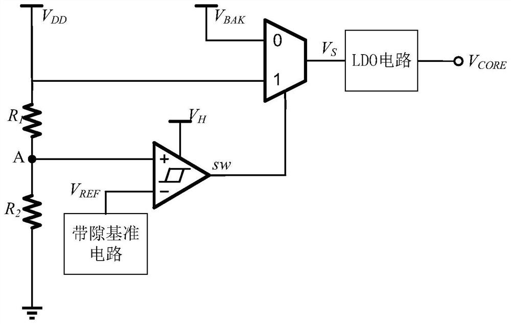
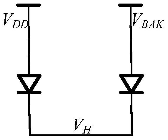
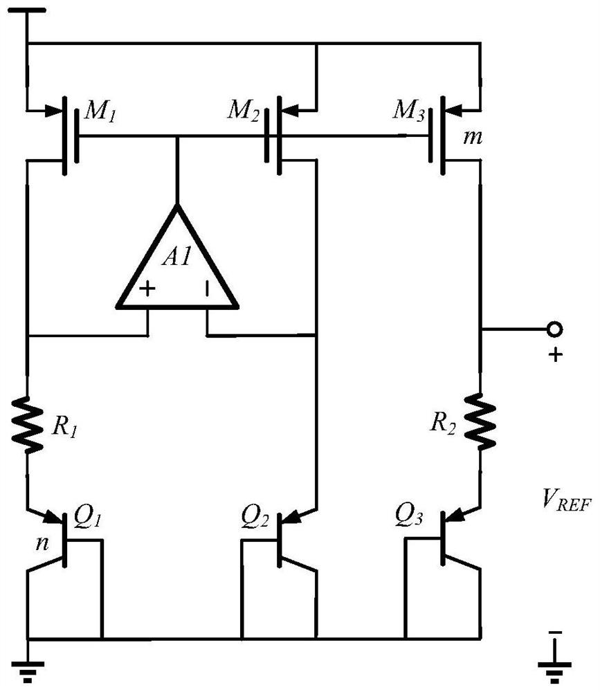
The invention belongs to the technical field of electronic circuits, and provides a multi-power supply switching circuit which is characterized by comprising the following steps: (1) a power supply VH obtained by connecting a power supply VDD and a backup power supply VBAK in parallel through a diode supplies power to a band-gap voltage reference, a hysteresis comparator and a gating control circuit; (2) designing a band-gap voltage reference to obtain a voltage VREF, and providing a stable reference voltage for a post-stage comparator and an LDO (Low Dropout Regulator) circuit; (3) designing a hysteresis comparator, adjusting a divider resistor according to a switching threshold to perform voltage division on VDD, and comparing with VREF to obtain a gating control signal; (4) designing a gating control circuit, utilizing a control signal sw obtained by a hysteresis comparator to obtain a gating control signal sw1 after level shift boosting, and gating a power supply to obtain a power supply voltage VS; and (5) an LDO circuit is designed according to the power supply voltage of a post-stage circuit, and the gated power supply VS supplies power to the LDO to obtain stable output voltage VCORE.
Description
technical field [0001] The invention belongs to the technical field of integrated circuits, and in particular relates to a multi-power supply switching circuit. Background technique [0002] With the advancement of integrated circuit technology, and the rapid development of wearable devices and Internet of Things technology, there are more and more chips of different types and applications, and accordingly, there are more and more level standards and power supply methods. Most of the existing chips on the market only support power supply or battery power supply within a small level range. An unexpected power failure or insufficient battery power will cause the chip to work abnormally, and even cause unpredictable risks to the entire system. [0003] The existence of the above problems puts forward higher requirements for chip design. Therefore, a circuit that is compatible with power supply and battery power supply is required. The circuit is compatible with a wide range of ...
Claims
Login to View More Application Information
Patent Timeline
 Patent Type & AuthorityApplications(China)
IPC IPC(8): H02J9/06
CPCH02J9/061
Inventor李威王涛杜涛罗和平
OwnerUNIV OF ELECTRONICS SCI & TECH OF CHINA