
Filtering device for mining water inlet station

A filter device and water inlet station technology, applied in the direction of filtration separation, filtration treatment, mining wastewater treatment, etc., can solve the problems of time-consuming and labor-consuming, loose parts, long time for disassembly and cleaning, etc., so as to avoid frequent disassembly and prolong the use Lifespan, the effect of extending the time period

Active Publication Date: 2022-06-17
ANHUI QIANYI INTELLIGENT EQUIP CO LTD
View PDF26 Cites 0 Cited by
  • Summary
  • Abstract
  • Description
  • Claims
  • Application Information

AI Technical Summary

Problems solved by technology

[0002] At present, among the equipment used in coal mines, sprinkler dust suppression devices and hydraulic support emulsion pump stations are usually used to use purified water to avoid failures during the use of equipment. Coal mines adopt the method of adding filters at the water inlet to purify water quality. However, this filtering method will cause some problems after being used for a period of time. Because the mine water dissolves many minerals during the flow process, it also contains a certain amount of coal chips, quicksand and other impurities. These solid impurities will pass through the filter. It is intercepted, because the intercepted amount is concentrated in one place, it is prone to clogging, because the accumulation is fast, people usually dispose of the filter regularly in a short period, but frequent disassembly is easy to cause parts to be broken Loose, and a single disassembly and cleaning takes a long time, which is time-consuming and labor-intensive, which affects the drainage efficiency

Method used


Image

  • Filtering device for mining water inlet station
  • Filtering device for mining water inlet station
  • Filtering device for mining water inlet station

Examples


Embodiment Construction

[0028] Embodiments of the present invention will be described below with reference to the accompanying drawings. During this process, in order to ensure the clarity and convenience of the description, we may exaggerate the width of the lines or the size of the components in the illustrations.

[0029] In addition, the following terms are defined based on the functions in the present invention, and may be different depending on the user, the operator's intention, or convention. Therefore, these terms are defined based on the entire content of this specification.

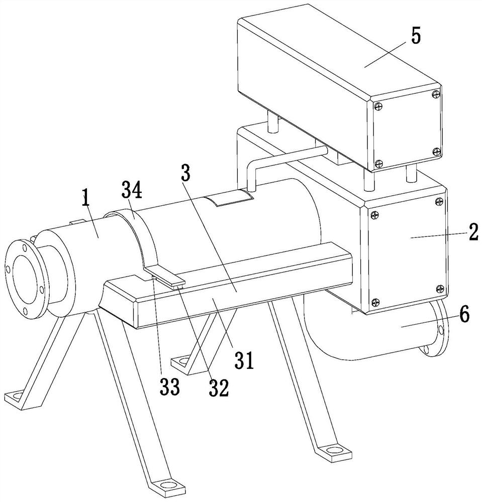
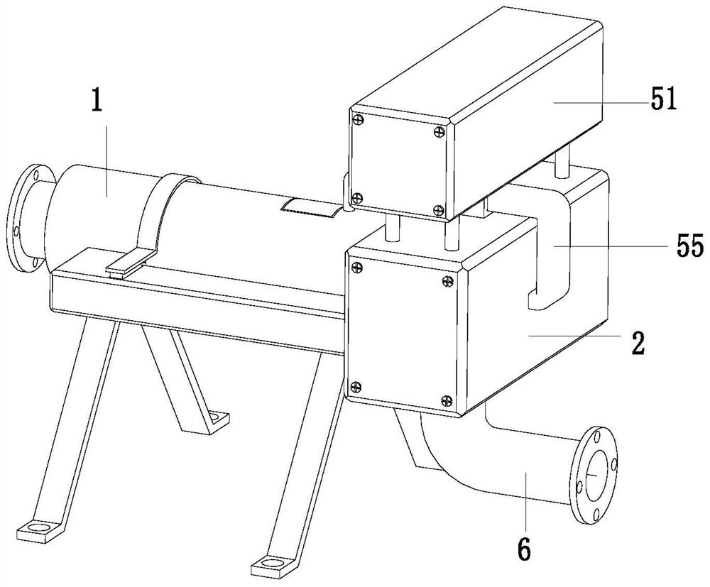
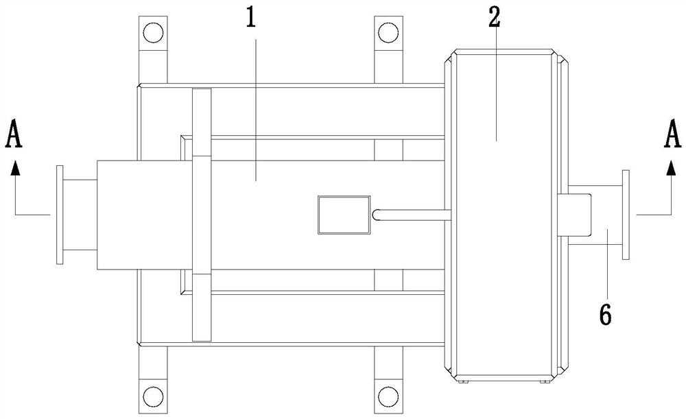
[0030] like Figure 1 to Figure 7 As shown in the figure, a filtration device for a mine water inlet station includes a conveying pipe 1, a centralized pipe 2, a distribution pipe 3, a filtering mechanism 4, a conveying mechanism 5 and a discharge pipe 6, and the right end of the conveying pipe 1 is installed with a centralized pipe 2, A distribution pipe 3 is installed between the front and rear ends of the conveyi...


PUM


Abstract

The invention relates to a mining water inlet station filtering device which comprises a conveying pipe, a centralizing pipe, distributing pipes, a filtering mechanism, a conveying mechanism and a discharging pipe, the centralizing pipe is installed at the right end of the conveying pipe, the distributing pipes are installed between the front end and the rear end of the conveying pipe and the centralizing pipe in a communicating mode, the filtering mechanism is installed in the conveying pipe, and the conveying mechanism is installed at the upper end of the centralizing pipe; discharge pipes are mounted at the lower ends of the concentration pipes. The device can solve the problems that in the flowing process of mine water, many mineral substances are dissolved, meanwhile, a certain amount of coal dust, quicksand and other impurities are contained, the solid impurities can be intercepted through a filter, the intercepted amount is concentrated at one position, the blocking phenomenon is likely to occur, and due to the fact that the accumulation speed is high, the blocking effect is poor. In the prior art, people usually treat the filter regularly in a short period, but parts are easy to loosen due to frequent disassembly, the time for single disassembly and cleaning is long, time and labor are consumed, and the drainage efficiency is influenced.

Description

technical field [0001] The invention relates to the technical field of mining equipment, in particular to a filtering device for a mining water inlet station. Background technique [0002] At present, the equipment used in coal mines usually adopts sprinkler dust suppression devices and hydraulic support emulsion pump stations, which need to use purified water to avoid failures during equipment use. Coal mines use filters at the water inlet to purify water. However, this filtration method will have some problems after a period of use. Since the mine water dissolves many minerals during the flow process, it also contains a certain amount of impurities such as coal dust and quicksand. Such solid impurities will pass through the filter. After being intercepted, because the intercepted amount is concentrated in one place, it is prone to blockage. Due to the fast accumulation rate, people usually dispose of the filter regularly in a short period, but frequent disassembly is easy ...

Claims


Application Information

Patent Timeline
Patent Type & Authority Applications(China)
IPC IPC(8): B01D29/01B01D29/58B01D29/96B01D29/68C02F9/04C02F103/10
CPCB01D29/01B01D29/58B01D29/96B01D29/68C02F1/001C02F1/008C02F2103/10
Inventor 孙伟李磊梁新魁
Owner ANHUI QIANYI INTELLIGENT EQUIP CO LTD
Learn More