
Grooving auxiliary device for diaphragm wall construction

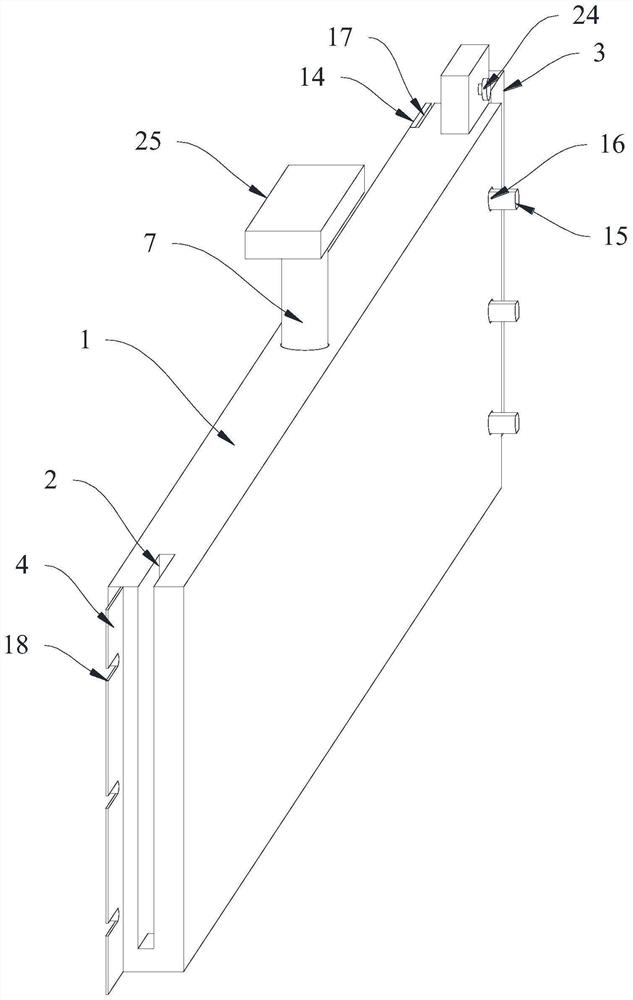
A construction and auxiliary device technology, applied in construction, sheet pile wall, infrastructure engineering and other directions, can solve the problems of irregular prefabricated cavity, inconvenient stacking storage and transportation, inability to stack and store regularly, etc. The effect of easy removal, easy stacking, transfer and transportation

Pending Publication Date: 2022-06-17
ZHEJIANG HUADONG ENG CONSTR MANAGEMENT +1
View PDF0 Cites 0 Cited by
  • Summary
  • Abstract
  • Description
  • Claims
  • Application Information

AI Technical Summary

Problems solved by technology

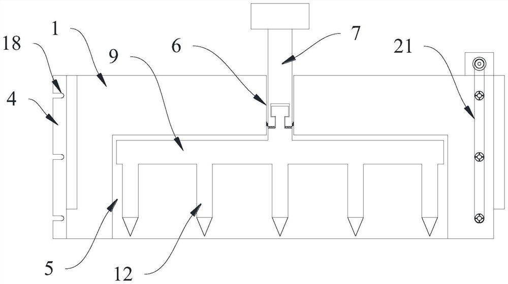
[0003] In order to stand stably on the ground, the existing lateral pressure formwork will be equipped with pointed cone columns at the bottom, and the side pressure formwork after the installation of the pointed cone columns will not be able to be regular during transportation and transfer due to the pointed cone columns. Stacked and stored, which makes it inconvenient to stack and store when transporting the side pressure formwork with pointed cone columns
At the same time, the existing side pressure formwork needs to be used by connecting when it is put into use, but when the side pressure formwork connected together will be put into use, concrete mud will seep from the joint, so that the side pressure formwork can be carried out through the side pressure formwork. The poured prefabricated cavity will appear irregular, and when the concrete slurry seeps out from the joint, it will cause trouble to remove the formwork on the opposite side

Method used


Image

  • Grooving auxiliary device for diaphragm wall construction
  • Grooving auxiliary device for diaphragm wall construction
  • Grooving auxiliary device for diaphragm wall construction

Examples


Embodiment Construction

[0023] In order to make those skilled in the art better understand the technical solutions of the present invention, the preferred embodiments of the present invention will be described below with reference to specific examples, but it should be understood that the accompanying drawings are only for illustrative description, and should not be construed as comprehension of the present invention. Limitation; in order to better illustrate this embodiment, some parts of the drawings will be omitted, enlarged or reduced, which do not represent the size of the actual product; for those skilled in the art, some well-known structures and their descriptions in the drawings may be The omission is understandable. The positional relationships described in the drawings are only for exemplary illustration, and should not be construed as limiting the present invention.

[0024] The present invention will be further described below in conjunction with the accompanying drawings and embodiments...


PUM


Abstract

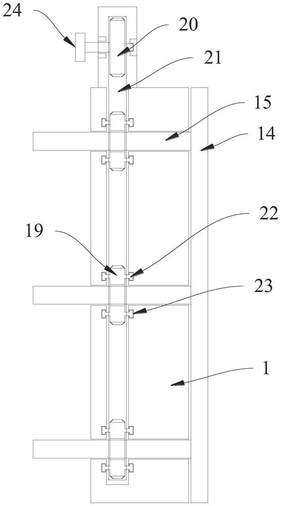
The invention provides a grooving auxiliary device for underground diaphragm wall construction, which is characterized in that a plurality of side pressing templates are connected in sequence, positioning devices are movably connected in the side pressing templates, connecting grooves are formed in the first side walls of the side pressing templates, and connecting convex columns matched with the connecting grooves are arranged on the second side walls of the side pressing templates; a sealing isolation pad is further arranged on the first side wall of the side pressing template, and a sealing connecting device matched with the sealing isolation pad is arranged on the second side wall of the side pressing template. A gap at the joint is sealed, and a user can easily and conveniently stack, transfer and transport the packaging box.

Description

technical field [0001] The invention relates to the technical field of construction engineering, in particular to a trough-forming auxiliary device for ground connection wall construction. Background technique [0002] In the construction process of the ground connecting wall, a prefabricated cavity is formed between the vertical side pressure formwork and the groove wall, and the built steel mesh frame is vertically erected in the prefabricated cavity, and then poured to form the ground connecting wall. The ground wall is generally more than ten meters long, and the height of the lateral pressure formwork is one meter. The above construction is the foundation construction at the bottom of the ground wall. [0003] In order to stand stably on the ground, the existing side pressure formwork will be equipped with a pointed cone column at the bottom. The side pressure formwork after adding the pointed cone column will not be regular due to the pointed cone column during transpo...

Claims


Application Information

Patent Timeline
Patent Type & Authority Applications(China)
IPC IPC(8): E02D5/18E02F5/02
CPCE02D5/18E02D5/185E02F5/02
Inventor 徐启良胡小坚吴明明张岗平顾文超王丙建孙忠秋刘雷胡俊刘家俊
Owner ZHEJIANG HUADONG ENG CONSTR MANAGEMENT
Learn More