
Wear-resistant plastic floor

A technology of plastic floor and wear-resistant layer, which is applied in the direction of construction, floor, building structure, etc., can solve the problems of wear-resistant layer wear, easy wear of the floor, and affecting the flatness of the wear-resistant layer, so as to ensure the flatness and disassembly The process is convenient and the effect of improving practicability

Pending Publication Date: 2022-06-17
河南省皮革塑料研究所有限公司
View PDF0 Cites 0 Cited by
  • Summary
  • Abstract
  • Description
  • Claims
  • Application Information

AI Technical Summary

Problems solved by technology

[0002] Plastic floor, that is, the floor laid with plastic materials, plastic floor can be divided into two types according to its use state: block material and roll material, according to its material can be divided into three types: hard, semi-hard and soft, according to its basic raw material It can be divided into several types such as polyvinyl chloride plastic, polyethylene plastic and polypropylene plastic. The existing plastic floor has poor wear resistance. During use, people always walk on the upper surface of the floor, making the floor The surface is easy to wear, which affects the use effect and aesthetics of the floor, so the existing floor surface will be equipped with a wear-resistant layer
[0003] The wear-resistant layer will be worn for a long time. Since the wear-resistant layer is generally bonded to the surface of the floor by heating, it is inconvenient to replace the wear-resistant layer. After the wear-resistant layer is removed, the surface of the floor may be damaged. Some jelly-like substances with uneven layers remain, which will affect the flatness of the subsequent wear-resistant layer after bonding

Method used


Image

  • Wear-resistant plastic floor
  • Wear-resistant plastic floor
  • Wear-resistant plastic floor

Examples


Embodiment Construction

[0033] The technical solutions in the embodiments of the present invention will be clearly and completely described below with reference to the accompanying drawings in the embodiments of the present invention. Obviously, the described embodiments are only a part of the embodiments of the present invention, but not all of the embodiments.

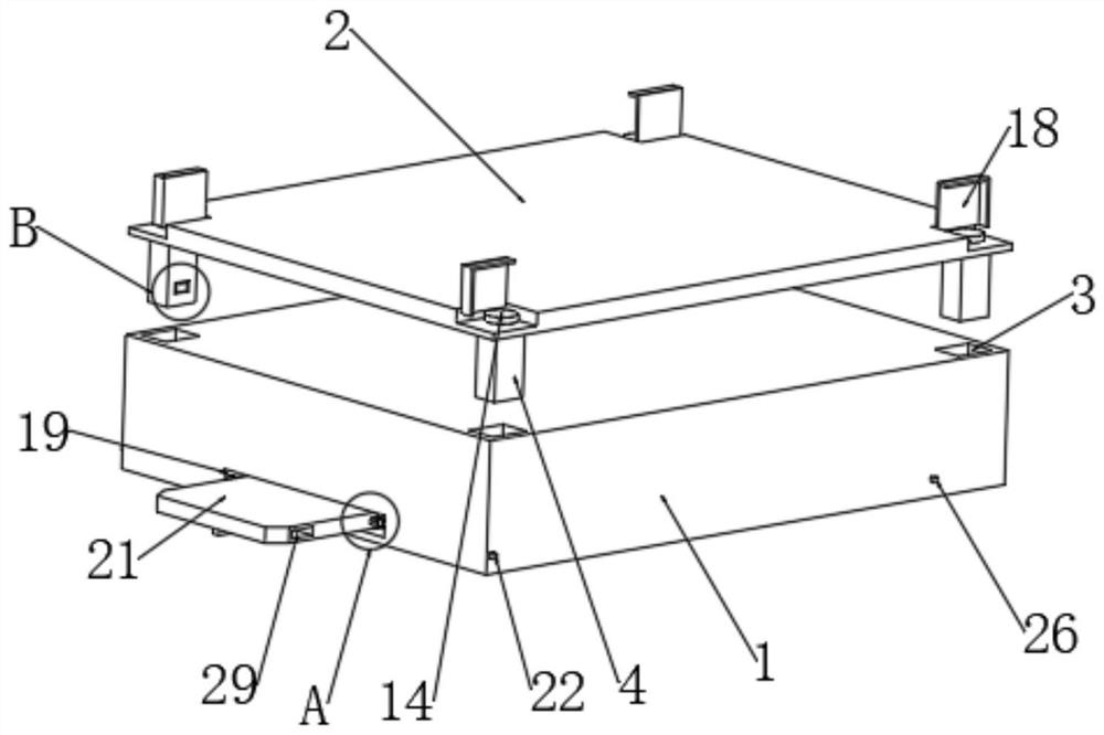
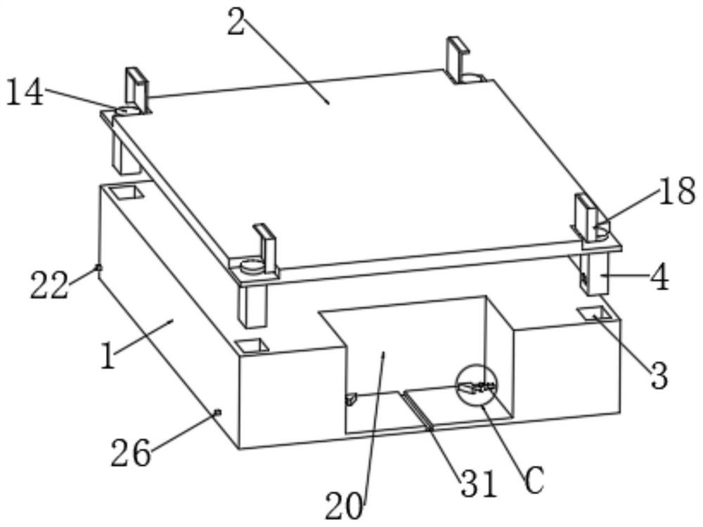
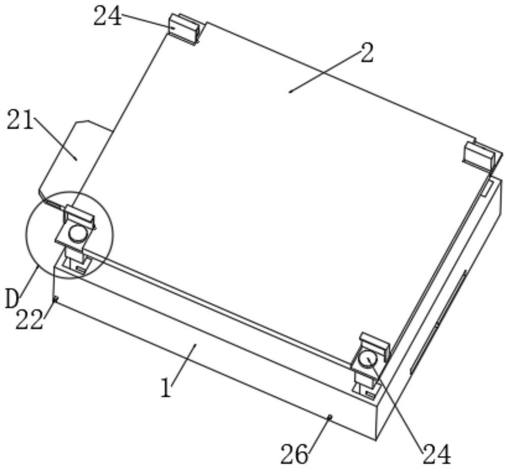
[0034] refer to Figure 1-10 , a wear-resistant plastic floor, comprising a board body 1, the upper surface of the board body 1 is provided with a wear-resistant layer 2;

[0035] The upper surface of the plate body 1 is vertically provided with four slots 3, and the lower surface of the wear-resistant layer 2 is vertically fixed and installed with four insertion rods 4 for inserting into the four slots 3;

[0036] The insertion rod 4 is provided with a locking assembly for locking itself in the slot 3. The locking assembly includes a spring rod 5 and an L-shaped locking plate 6 fixedly installed at one end of the spring rod 5. The insertio...


PUM


Abstract

The wear-resistant plastic floor comprises a floor body, and a wear-resistant layer is arranged on the upper surface of the floor body; four inserting grooves are vertically formed in the upper surface of the plate body, and four inserting rods used for being inserted into the four inserting grooves are vertically and fixedly installed on the lower surface of the wear-resisting layer. A locking assembly is arranged in the inserting rod, the locking assembly comprises a spring rod and an L-shaped locking plate fixedly installed at one end of the spring rod, and a locking groove used for allowing the locking plate to be inserted therein is formed in one groove wall of the inserting groove; a driving part is arranged in the inserting rod and used for providing driving force for the locking plate to move. A user can quickly realize the disassembly and assembly work between the wear-resistant layer and the plate body through the matching between the locking assembly and the driving part, heating and bonding are not needed, the operation is convenient and quick, and the flatness of the wear-resistant layer after replacement can be ensured.

Description

technical field [0001] The invention relates to the technical field of plastic floors, in particular to a wear-resistant plastic floor. Background technique [0002] Plastic floor, that is, the floor laid with plastic materials, plastic floor can be divided into two kinds according to its use status: block material and coil material, according to its material can be divided into three kinds of hard, semi-hard and soft, according to its basic raw materials It can be divided into several types such as polyvinyl chloride plastic, polyethylene plastic and polypropylene plastic. The existing plastic floor has poor wear resistance. During the use process, people always walk on the upper surface of the floor, making the floor The surface is easy to wear, which affects the use effect and aesthetics of the floor, so the existing floor surface will be provided with a wear-resistant layer. [0003] The wear-resistant layer will wear for a long time. Since the wear-resistant layer is g...

Claims


Application Information

Patent Timeline
Patent Type & Authority Applications(China)
IPC IPC(8): E04F15/02E04F15/10
CPCE04F15/107E04F15/02005
Inventor 马志军于仙杏
Owner 河南省皮革塑料研究所有限公司
Learn More