Foundation pit post-installation beam string structure construction method

A construction method and technology for foundation pits, which are applied in basic structure engineering, excavation, construction, etc., can solve problems such as affecting the convenience of earthwork excavation, affecting the arrangement of steel supports for string beams, etc., and achieve increased convenience, ingenious design, and easy installation. Effect

Pending Publication Date: 2022-06-21
上海巨鲲科技有限公司
0 Cites 0 Cited by

AI-Extracted Technical Summary

Problems solved by technology

[0003] In the prior art, when excavating the steel support of the string beam of the foundation pit, the unearthed position is not allowed to stay at the position of the steel support of the st...

Method used

The present invention reserves the excavation opening at the position of the string beam, and through the way of installing the string beam at a specific position, avoids the impact of unearthed on the steel support, increases the convenience of foundation pit earthwork excavation; from the reserved soil slope to the pre-excavation The reserved soi...

Abstract

The invention relates to a construction method for installing a beam string structure after a foundation pit. The construction method comprises the following steps that S1, a site is excavated to the elevation of a steel support installation plane; s2, beam string structures and steel supports except for the unearthed position are installed; s3, soil is excavated in the site and concentrated in the area right opposite to the beam string structure, and in the soil excavation process, a soil slope with a certain gradient is reserved at the soil excavation position of the beam string structure and used for allowing an earthwork vehicle to go in and out and balancing the soil pressure outside the pit; s4, after the other parts except the unearthed position are excavated, a part of soil is collected from the slope bottom to the slope body of the soil slope, a soil table used for installing and balancing soil pressure is reserved, and a beam string structure at the unearthed position is installed; s5, prestress is applied to the beam string structure at the unearthed position; and S6, the reserved soil platform is excavated out of the site through a long-arm excavator. The soil outlet is reserved in the position of the beam string structure, the influence of soil outlet on the steel support is avoided through the method that the beam string structure is installed at the specific position, and the foundation pit earthwork excavation convenience is improved.

Application Domain

Excavations

Technology Topic

Soil scienceGeotechnical engineering +4

Image

  • Foundation pit post-installation beam string structure construction method
  • Foundation pit post-installation beam string structure construction method
  • Foundation pit post-installation beam string structure construction method

Examples

  • Experimental program(1)

Example Embodiment

[0027] The present invention will be further described below with reference to the accompanying drawings and specific embodiments.
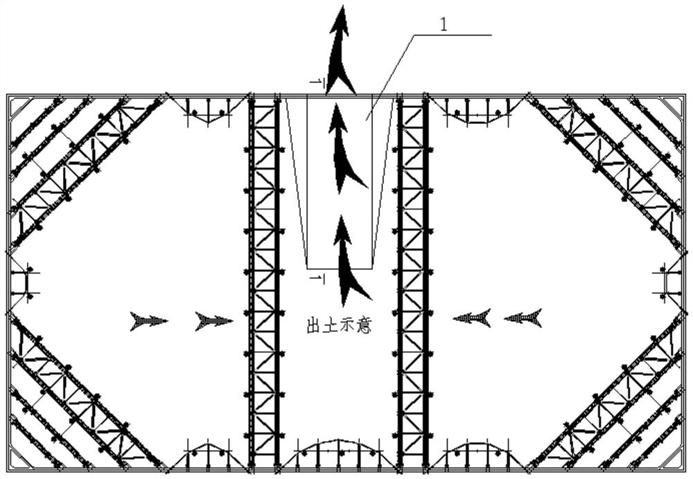
[0028] see Figure 1-Figure 5 , a construction method for post-installation string beams in a foundation pit, comprising the following steps:
[0029] like figure 1 As shown, S1, excavate the site to the level of the steel support installation plane; S2, install the string beam and steel support except the excavation position; S3, excavate the soil in the site and concentrate it in the area opposite to the string beam, during the excavation process, At the excavation position of Zhangxianliang, a certain slope of soil is reserved for earthmoving vehicles to enter and exit, and to balance the earth pressure outside the pit.
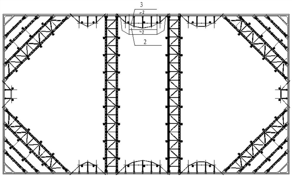
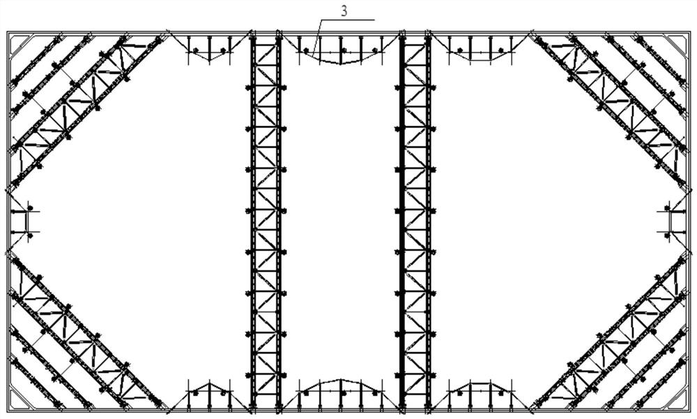
[0030] like figure 2 As shown in S4, after the excavation of the remaining part except the unearthed position is completed, the soil slope collects a part of the soil from the bottom of the slope to the slope body, and is reserved for the soil platform for installation and balance of earth pressure, and the tension beam at the unearthed position is installed; S5, Apply prestress to the tension beam at the excavated location.
[0031] like image 3 As shown, S6, using a long-arm excavator to excavate the reserved soil platform outside the site.
[0032] In this example, see Figure 4 , in step S3, the upper surface of the soil platform is higher than the height of the concrete crown beam 4; refer to Figure 5 , in step S4, the upper surface of the soil platform is lower than the height of the concrete beam 4. .
[0033] In this example, see figure 2 , the horizontal length of the upper surface of the soil platform is greater than the height loss of the string beam.
[0034] In this example, see Figure 5 , the longitudinal section of the soil platform is trapezoidal.
[0035] In this example, see Figure 4 and Figure 5 , the string beam at the excavation position is supported by the upright column 5 which is driven into the foundation pit in advance.
[0036] The invention reserves the excavation port at the position of the string beam, and the method of installing the string beam after the specific position avoids the influence of the excavation on the steel support, and increases the convenience of excavation of the foundation pit; from the reserved soil slope to the reserved soil platform, The conversion process is convenient, and each has a good effect. The reserved soil slope is convenient for excavation, and the reserved soil platform can be more convenient for the installation of the string beam at the excavation position, and at the same time, it can balance the surrounding earth pressure, and the design is ingenious.
[0037] The above are the preferred embodiments of the present invention, and those of ordinary skill in the art can also carry out various transformations or improvements on this basis. Without departing from the general concept of the present invention, these transformations or improvements should belong to the claimed protection of the present invention. within the range.

PUM

no PUM

Description & Claims & Application Information

We can also present the details of the Description, Claims and Application information to help users get a comprehensive understanding of the technical details of the patent, such as background art, summary of invention, brief description of drawings, description of embodiments, and other original content. On the other hand, users can also determine the specific scope of protection of the technology through the list of claims; as well as understand the changes in the life cycle of the technology with the presentation of the patent timeline. Login to view more.

Similar technology patents

Transmission-type display

ActiveUS20160320623A1improve convenience
Owner:SEIKO EPSON CORP

Method for paying through intermediate platform and paying system thereof

InactiveCN101470875Aavoid property damageImprove convenience
Owner:ALIBABA GRP HLDG LTD

Network scanning system

InactiveUS20050057780A1improve conveniencelow cost
Owner:CANON DENSHI KK

Classification and recommendation of technical efficacy words

  • Simple conversion process
  • Improve convenience

Cable partial discharge mode identification method based on depth sample enhancement

ActiveCN112557833ASimple conversion processAvoid errors
Owner:JIAOZUO POWER SUPPLY COMPANY OF STATE GRID HENAN ELECTRIC POWER

Image display method and apparatus

ActiveUS20130040623A1improve conveniencemaximize utility
Owner:LG ELECTRONICS INC

Voice control method and device

Owner:LE SHI ZHI XIN ELECTRONICS TECH TIANJIN

Continuously operable seat-reclining device for vehicles

InactiveUS20050110322A1actuate load be reduceimprove convenience
Owner:DAS CO LTD
Why Eureka
Try Eureka