

Ceramic humidity sensor
A humidity sensor and ceramic technology, applied in instruments, scientific instruments, measuring devices, etc., can solve the problem of oxygen reducing the accuracy of humidity measurement, and achieve the effect of improving accuracy
Pending Publication Date: 2022-06-21
江苏惟哲新材料有限公司
View PDF0 Cites 0 Cited by
- Summary
- Abstract
- Description
- Claims
- Application Information
AI Technical Summary
Problems solved by technology
[0003] In order to solve the problem that the existing zirconia ceramic humidity sensor has the problem that the presence of oxygen in the ambient gas will reduce the accuracy of humidity measurement when measuring humidity, the present invention provides a ceramic humidity sensor, which can pump out oxygen in advance, in the absence of oxygen In the presence of ionized water, the current value is obtained directly to obtain the humidity value, which improves the accuracy of humidity measurement
Method used
View moreImage
Smart ImageViewing Examples


Examples
Embodiment Construction
Login to View More PUM
 Abstract
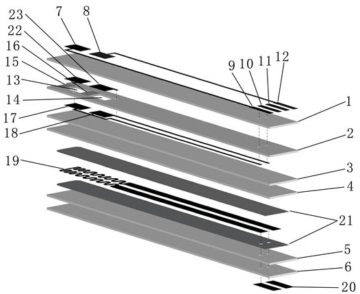
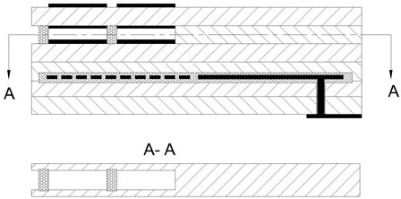
The invention provides a ceramic humidity sensor which can pump out oxygen in advance, ionize water in the absence of oxygen to directly obtain a current value so as to obtain a humidity value and improve the humidity measurement accuracy, and is characterized in that a first outer electrode and a second outer electrode are arranged on the upper side of one end of a first zirconia ceramic layer; the first outer electrode and the second outer electrode are respectively connected with a first pin and a fourth pin of the first electrode pin through leads; one end of the second zirconia ceramic layer is provided with a first cavity and a second cavity, the positions of the first cavity and the second cavity correspond to the positions of the first outer electrode and the second outer electrode respectively, the first cavity is communicated with the outside through a first porous layer, the first cavity and the second cavity are communicated through a second porous layer, and the lower sides of the first cavity and the second cavity are provided with a first inner electrode and a second inner electrode respectively. The first inner electrode and the second inner electrode are respectively connected with the second pin and the third pin of the first electrode pin through wires and via holes.
Description
Technical field [0001] The invention is a humidity sensor technology field, especially involving a ceramic humidity sensor. Background technique [0002] In the existing technology, the humidity measurement of the humidity sensor of the oxidation ceramics is generally used for humidity measurement at high temperature. The measurement method is the difference between the total current values obtained by obtaining high voltage and ionizing oxygen and water and the current value obtained by the low -electrocable oxygen.This difference is the current value obtained by ionizing water, and then the corresponding humidity value is used to use the difference; the defects existing above are: because the current value obtained by obtaining the electric ionization water by obtaining the current difference is obtained, then the ionizing oxygen obtains the ionization oxygen obtained by obtaining the ionization oxygen.The accuracy of the current value will affect the accuracy of the current va...
Claims
Login to View More Application Information
Patent Timeline
 IPC IPC(8): G01N27/70
CPCG01N27/70
Inventor陈江翠马浩然陈志赵峰
Owner江苏惟哲新材料有限公司