Automatic welding equipment for header welding

An automatic welding and header technology, which is applied in the direction of welding equipment, auxiliary welding equipment, welding/cutting auxiliary equipment, etc., can solve the problems that it is difficult to ensure that the welding gun is caught in time, slow down the work efficiency of workers, and troublesome disassembly, etc., to improve Effects of practicality and creativity, increased practicality, and convenient operation

Active Publication Date: 2022-06-24
JIANGSU PROVINCE XUZHOU TECHNICIAN INST
View PDF5 Cites 0 Cited by
  • Summary
  • Abstract
  • Description
  • Claims
  • Application Information

AI Technical Summary

Problems solved by technology

In modern industrial production, the mechanization and automation of the welding production process is an inevitable trend in the modernization of the welding mechanism manufacturing industry. The existing device requires workers to operate with both hands during the disassembly process of the welding torch. It is inconvenient to catch it in time, which greatly slows down the work efficiency of workers

Method used


Image

  • Automatic welding equipment for header welding
  • Automatic welding equipment for header welding
  • Automatic welding equipment for header welding

Examples


Embodiment 1

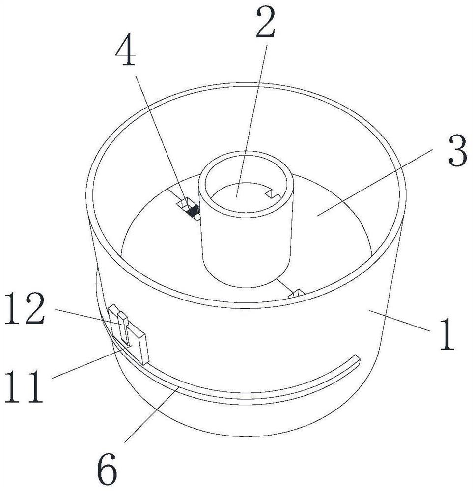
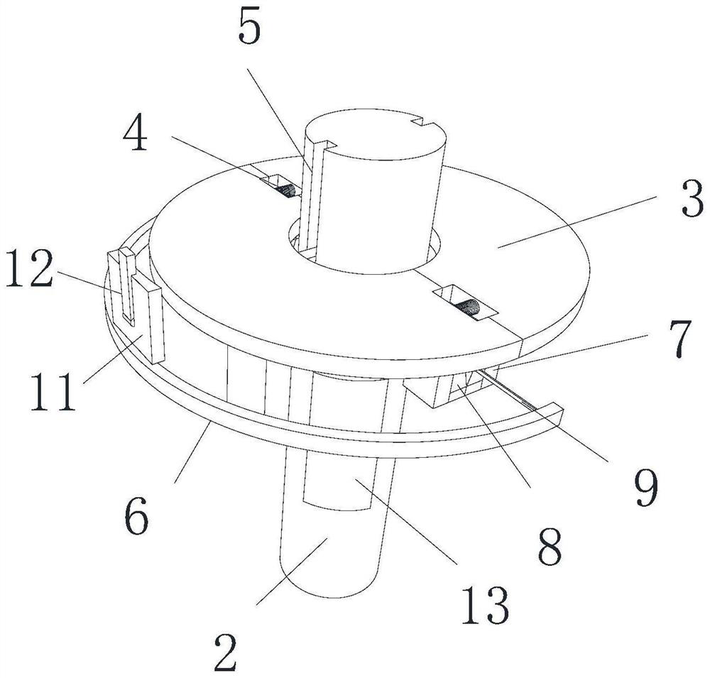
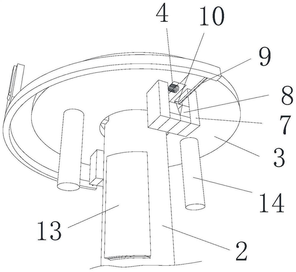
[0030] Embodiment 1: A kind of automatic welding equipment for header welding, such as Figure 1-Figure 3As shown, including a manipulator 1, the manipulator 1 is a hollow circular ring, the inner cavity of the manipulator 1 is inserted with a welding gun 2, the hollow part of the manipulator 1 is provided with a fixing device, and the fixing device includes a fixed splint 3, and the number of the fixed splints 3 is Two, the two fixed splints 3 are symmetrically arranged in the manipulator 1, and the two fixed splints 3 form a circular ring that matches the shape of the welding gun 2, and the bottoms of the two fixed splints 3 are fixedly installed with support columns for support. 14. The other end of the support column 14 is in contact with the bottom surface of the inner cavity of the manipulator 1. The side wall of the manipulator 1 is provided with a disengagement device, and the disengagement device includes a deceleration plate 13 for deceleration. It is located at the ...

Embodiment 2

[0032] Embodiment 2: A kind of automatic welding equipment for header welding, such as Figure 1-Figure 3 As shown, including a manipulator 1, the manipulator 1 is a hollow circular ring, the inner cavity of the manipulator 1 is inserted with a welding gun 2, the hollow part of the manipulator 1 is provided with a fixing device, and the fixing device includes a fixed splint 3, and the number of the fixed splints 3 is Two, the two fixed splints 3 are symmetrically arranged in the manipulator 1, and the two fixed splints 3 form a circular ring that matches the shape of the welding gun 2, and the bottoms of the two fixed splints 3 are fixedly installed with support columns for support. 14. The other end of the support column 14 is in contact with the bottom surface of the inner cavity of the manipulator 1. The side wall of the manipulator 1 is provided with a disengagement device, and the disengagement device includes a deceleration plate 13 for deceleration. It is located at the...


PUM


Abstract

The invention relates to the technical field of welding equipment, and discloses automatic welding equipment for header welding, which comprises a manipulator, the manipulator is in a hollow circular ring shape, a welding gun is inserted into an inner cavity of the manipulator, and a fixing device is arranged at the hollow part in the manipulator and comprises a fixing clamping plate; the two fixing clamping plates are symmetrically located in the manipulator, supporting columns used for supporting are fixedly installed at the bottoms of the two fixing clamping plates, the other ends of the supporting columns make contact with the bottom face of an inner cavity of the manipulator, and a disengaging device is arranged on the side wall of the manipulator and comprises a speed reducing plate used for reducing speed. According to the welding gun falling-off device, the falling-off device is used, the speed of the welding gun is reduced through the speed reducing block through the arrangement of the speed reducing plate when the welding gun falls off, the situation that the welding gun is damaged due to the too high falling speed is avoided, in this way, the falling-off speed of the welding gun is greatly increased, the working efficiency is improved, and the practicability of the device is improved.

Description

technical field [0001] The invention relates to the technical field of welding equipment, in particular to an automatic welding equipment used for header welding. Background technique [0002] In the past 20 years, with the development of digitization, automation, computer, and mechanical design technology, and the high emphasis on welding quality, automatic welding has developed into an advanced manufacturing technology, and automatic welding equipment has played an important role in the application of various industries. The role is getting bigger and bigger, and the scope of application is expanding rapidly. In modern industrial production, the mechanization and automation of the welding production process is an inevitable trend of the modernization development of the welding mechanism manufacturing industry. The existing device requires workers to operate with both hands during the disassembly process of the welding gun, which is troublesome and difficult to ensure that ...

Claims


Application Information

Patent Timeline
Patent Type & Authority Applications(China)
IPC IPC(8): B23K37/02B23K37/00
CPCB23K37/02B23K37/00Y02P70/10
Inventor 宋娟
Owner JIANGSU PROVINCE XUZHOU TECHNICIAN INST
Why Eureka
Try Eureka